
Single Op-Amp Bandpass Filter circuit
A bandpass filter is a critical component in various electronic applications, including communications, audio processing, and signal conditioning. It is designed to isolate a particular frequency range, enabling the desired signals to be amplified or processed while attenuating unwanted noise and interference.
Typically, a bandpass filter can be implemented using passive or active components. Passive filters may consist of resistors, capacitors, and inductors arranged in specific configurations, such as RLC circuits, to achieve the desired frequency response. Active bandpass filters, on the other hand, incorporate operational amplifiers (op-amps) along with passive components to enhance performance, allowing for better gain and impedance matching.
The design of a bandpass filter involves determining the center frequency (fc), the bandwidth (BW), and the quality factor (Q). The center frequency is the midpoint of the passband, while the bandwidth is the difference between the upper and lower cutoff frequencies. The quality factor represents the selectivity of the filter, with higher Q values indicating a narrower bandwidth and sharper roll-off characteristics.
In practical applications, bandpass filters are utilized in radio transmitters and receivers, where they help to select the desired communication channel while rejecting adjacent frequencies. Additionally, in audio systems, they are used to enhance specific frequency ranges, such as bass or treble, contributing to improved sound quality.
The implementation of a bandpass filter requires careful consideration of component values and circuit topology to ensure that the desired frequency response is achieved. Simulation tools are often employed during the design phase to validate performance before physical construction. The final circuit can be tested using spectrum analyzers to confirm that it meets the specified frequency response and attenuation characteristics.A bandpass filter passes a range of frequencies while rejecting frequencies outside the upper and lower limits of the passband. The range of frequencies to be passed is called the passband and extends from a point below the center frequency to a point above the center frequency where the output voltage falls about 70% of the output voltage at the center frequency..
🔗 External reference
Related Circuits
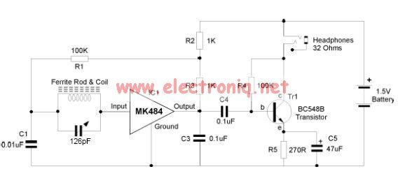
The MK484 AM radio circuit offers a comprehensive solution that includes an RF amplifier, detection, and automatic gain control (AGC) circuit. It requires only a few external components to achieve a high-quality AM tuner. The circuit features an input...
BFO is a simple device which helps us to listen SSB and CW transmissions. Reception of SSB and CW signals requires a product detector or BFO (Beat Frequency Oscillator) to reinsert the missing carrier. This circuit is very simple...
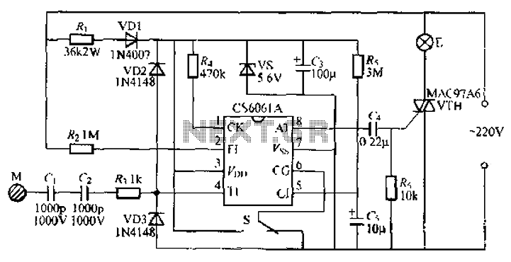
The CS6061A integrated circuit is designed for touch-step dimming lights. It features a two-state female switching function and is reliable, capable of adapting to long cables and larger touch-sensitive pad loads (400pF). The collector circuit of the CS6061A utilizes...
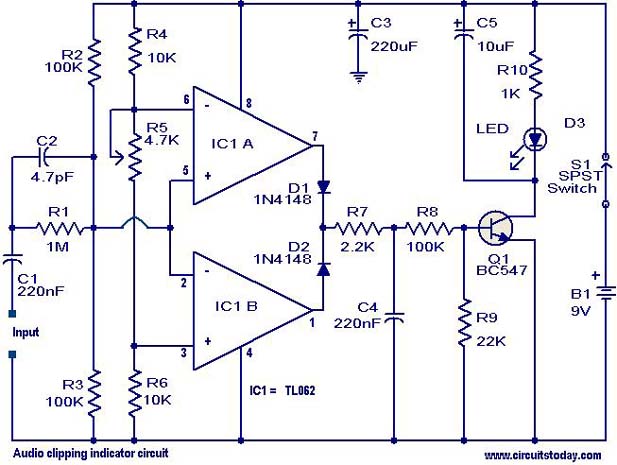
This circuit is designed to detect clipping in a specific waveform. Clipping occurs when the amplitude of a waveform decreases before reaching its expected limit. The circuit activates an LED as an indication that the tested signal is experiencing...
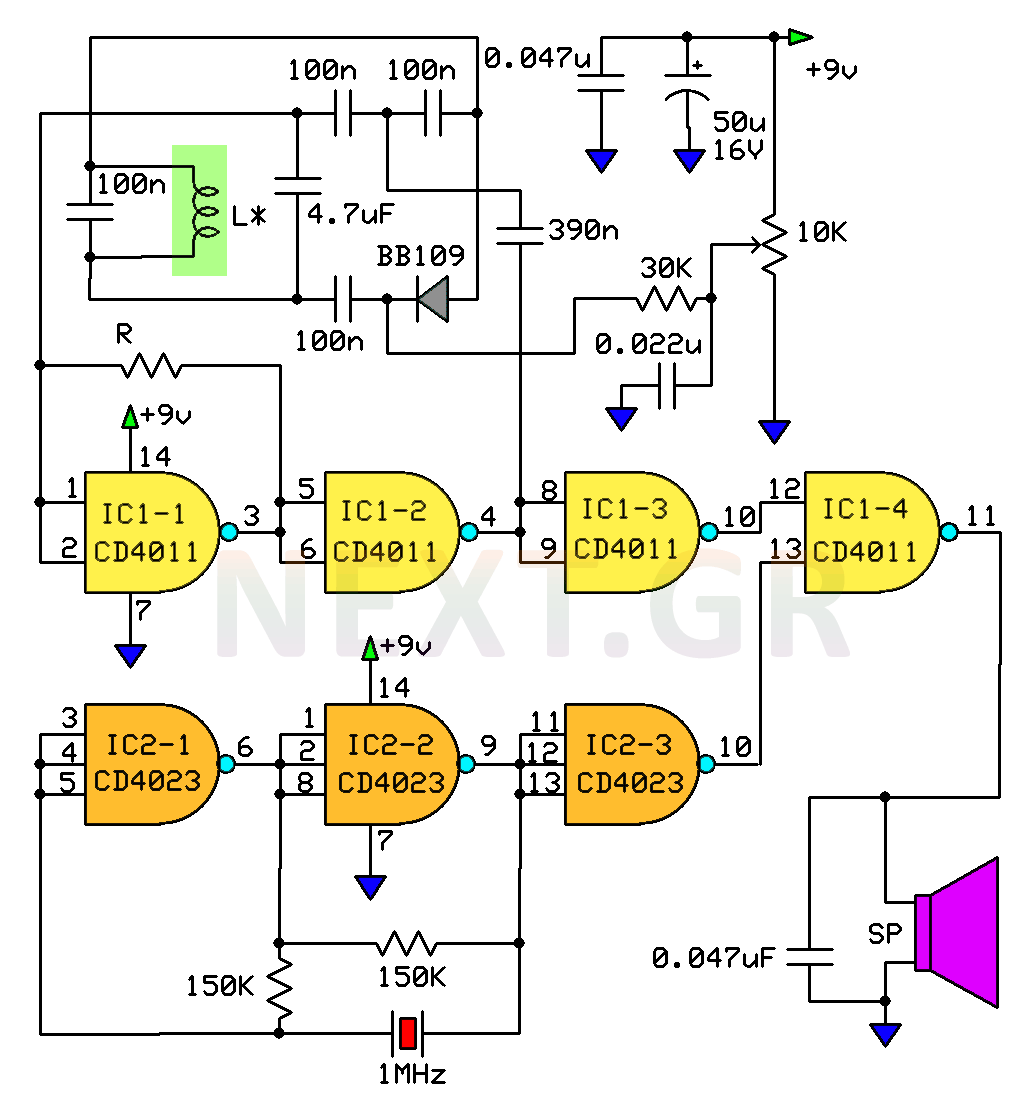
This circuit is a metal detector designed to detect large metallic objects at depths ranging from 2 to 3 meters, depending on the size of the object and the type of soil. The construction is straightforward, making it accessible...
The PIC16C57-RCT is a communication single-chip microcomputer integrated circuit that is commonly utilized in the Qiao Xing series of IC card management telephones. The PIC16C57-RC integrated circuit features a pulse and dual-tone dialing circuit, memory data and clock circuit,...
Warning: include(partials/cookie-banner.php): Failed to open stream: Permission denied in /var/www/html/nextgr/view-circuit.php on line 713
Warning: include(): Failed opening 'partials/cookie-banner.php' for inclusion (include_path='.:/usr/share/php') in /var/www/html/nextgr/view-circuit.php on line 713