
MSC1210 Reset Circuit
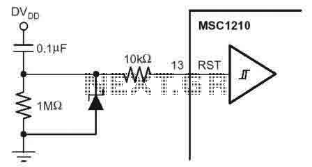
The external reset circuit for the MSC1210 is designed to ensure reliable operation of the device by providing various reset sources. The RST pin plays a critical role in this process. When the RST pin is driven high for a duration of two oscillator periods (tOSC), the device halts all operations and disables the crystal oscillator. This action also ensures that all digital pins are set to a high state, effectively preparing the device for a reset. Following this high state, the RST pin must be driven low to initiate the reset sequence.
In the typical reset circuit configuration, a 10 kΩ resistor is employed in series with the RST pin. This resistor serves as a pull-up mechanism, ensuring that the RST pin remains high when not being actively driven low. The reset circuit can be triggered by multiple sources, including power-on reset, which occurs when power is applied to the system, external reset triggered by an external signal, software reset initiated by the microcontroller, watchdog timer reset to recover from unresponsive states, and brownout reset to protect the system during voltage drops.
The schematic representation of this reset circuit is vital for engineers designing systems that incorporate the MSC1210, as it illustrates the connections and components necessary for effective reset management. The inclusion of the 10 kΩ resistor is particularly important for maintaining the integrity of the reset signal across various operating conditions. This design ensures that the MSC1210 and any connected microcontroller or memory components operate reliably, minimizing the risk of erroneous states due to improper reset conditions.According to the MSC1210 datasheet, you will perform an external reset by taking RST pin high for two tOSC periods as this stops device operation, crystal oscillation, causes all digitall pins to be pulled high from that point and then followed by taking the RST pin low that initiates the reset procedure. Herein a typical reset circuit of the MSC1210-a precision Analog-to-Digital Converter (ADC) with 8051 Microcontroller and Flash Memory schematic that can be done from the following sources: power-on reset, external reset, software reset, watchdog timer reset, and brownout reset. The figure (click to enlarge) shows a recommended external reset circuit for the MSC1210 with the serial 10kOhm resistor recomendation for any configuration of this reset type.
🔗 External reference
Related Circuits
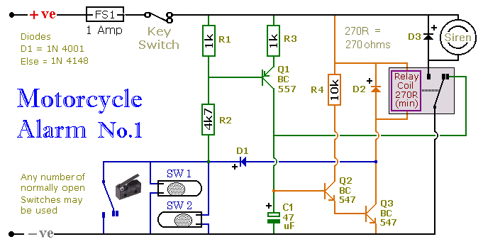
This circuit includes a timed output and an automatic reset feature. It can be manually operated using a key switch or a concealed switch. By incorporating an external relay, the circuit will automatically engage or immobilize the machine each...
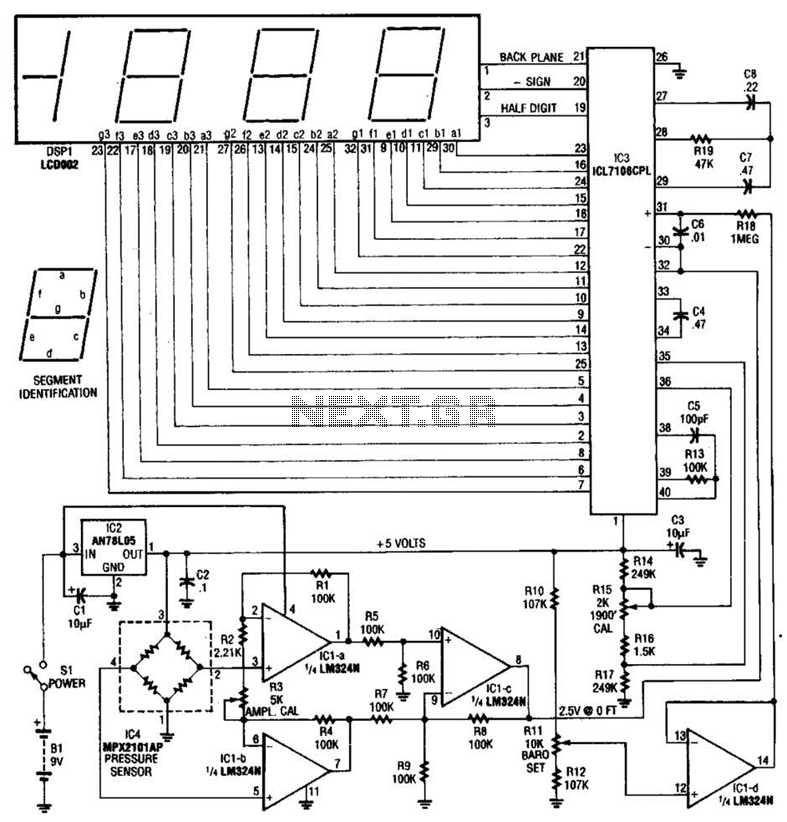
A pressure sensor (IC4) is utilized in conjunction with a DC amplifier to convert the bridge output from IC4 into a single-ended voltage. IC1 provides a reference voltage for setting the barometric pressure. IC3 is an A/D converter produced...
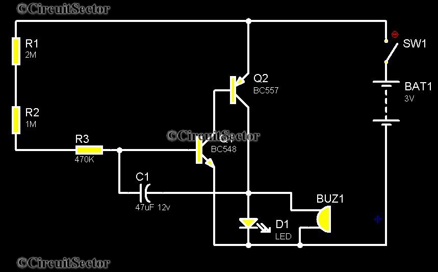
Telephones are declining globally; however, India has over 350 million mobile phone users, alongside a significant number of traditional telephone users. This telephone timer is designed to save costs by controlling unnecessary time spent during phone calls. This simple...
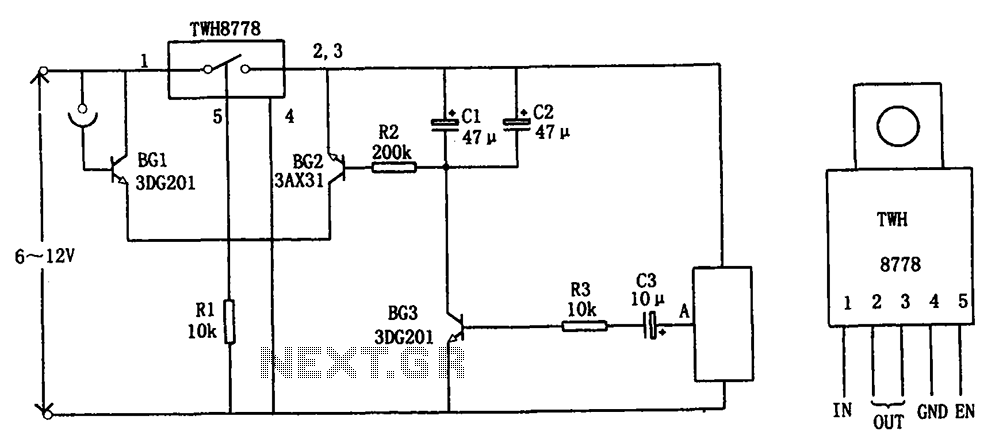
The circuit illustrated in FIG X pertains to automatic circuitry for US recorders. It primarily utilizes a new power switching device, TWH8778, which simplifies the design and eliminates the need for extensive debugging. The TWH8778's configuration and pin functions...
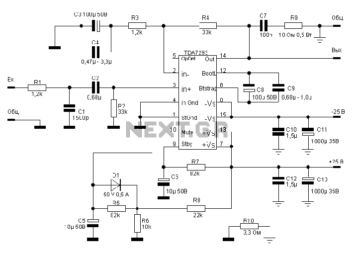
The TDA7293, produced by the ST (SGS-THOMSON) company, is a high-power, high-voltage DMOS high-fidelity amplifier integrated circuit (IC) with a rated output power of 100W. It operates at a maximum voltage of 120V. The key specifications include a dual...
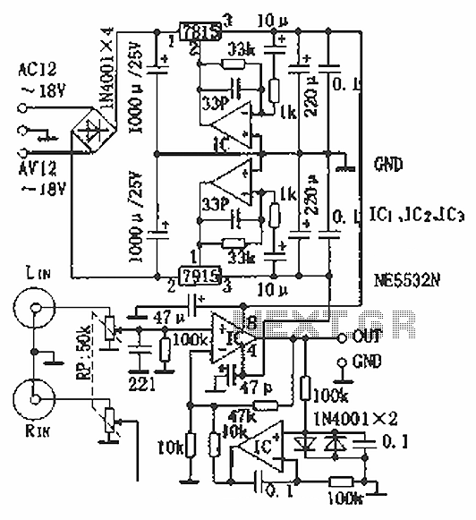
Hi-fi headphones possess a wide frequency response and low distortion, making them incomparable to desktop Hi-Fi audio systems, particularly when compared to some branded headphones and even high-quality speakers. High-fidelity headphones are designed for music listening, offering high resolving...
Warning: include(partials/cookie-banner.php): Failed to open stream: Permission denied in /var/www/html/nextgr/view-circuit.php on line 713
Warning: include(): Failed opening 'partials/cookie-banner.php' for inclusion (include_path='.:/usr/share/php') in /var/www/html/nextgr/view-circuit.php on line 713