
Simple Telephone Timer Circuit PCB
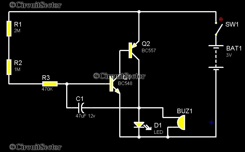
The telephone timer circuit typically consists of a few essential components: a microcontroller or timer IC, a piezo buzzer, an LED, and a power supply. The microcontroller or timer IC is programmed to count the elapsed time from the moment the user activates the timer. When the call connects, the user presses a switch to start the timer.
The piezo buzzer serves as an audible alert, producing a sound at the end of each minute to notify the user that a minute has elapsed. The LED provides a visual cue, flashing in synchronization with the buzzer. This dual alert system ensures that users remain aware of their call duration, promoting efficient communication and cost savings.
The circuit may also include a power management section to ensure that it operates efficiently and conserves battery life. A small capacitor can be used to smooth out power supply fluctuations, while a resistor limits the current to the LED and the buzzer, protecting them from excessive current that could lead to damage.
In terms of layout, the components should be arranged to minimize the length of the connections, reducing noise and potential interference. The microcontroller should be placed centrally to easily connect to the buzzer and LED. Additionally, the circuit should have a user-friendly interface, with clearly marked activation buttons and indicators for the timer status.
Overall, this telephone timer circuit is a practical solution for users looking to manage their call duration effectively, contributing to cost savings in telecommunication expenses.Telephones are reaching its death point all over the world. however there is more than 350 million mobile phone users in india, but there are tremendous number of telephone users are there also. Well, this telephone timer is designed to help saving by controlling unnecessary time taken during pone calls.
This simple timer circuit is better in its accuracy because it is manually put on by the user when the call connects at the other end. The piezo buzzer provided in the circuit makes a beep along with an LED flash during every passing minute. The time will not so accurate, but there is not more than 2-3 seconds variation. you have to put ON the timer at the moment when call starts. Then it will do the job of alerting during each minute to suppress your conversation and save money. 🔗 External reference
Related Circuits
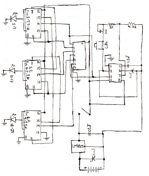
Here is the schematic for the circuit. Solder all the components onto a perfboard. The drawings may not be very clear. Essentially, the 555 timer generates a pulse. The circuit utilizes a 555 timer IC configured in astable mode, which...
The metal detector circuit comprises an oscillator and a sound-light alarm circuit. The oscillator circuit includes an inductor (L), a capacitor (C1), a sensor switch integrated circuit (IC1) that integrates the oscillator, detector, comparator circuit, and peripheral components. The...
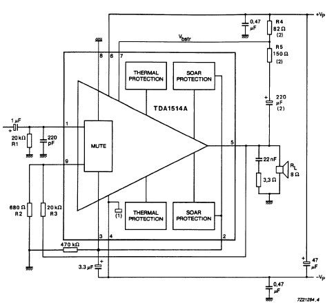
The TDA1514 audio amplifier circuit design is an electronic project capable of delivering high audio power output using a specialized audio integrated circuit (IC) and a few common components. Manufactured by Philips Semiconductor, the TDA1514 audio IC can provide...
This circuit is a small +5V power supply, which is useful when experimenting with digital electronics. Small inexpensive wall transformers with variable output voltage are available from any electronics shop and supermarket. Those transformers are easily available, but usually...
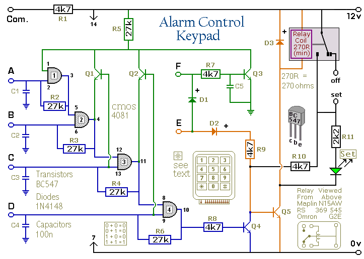
Pressing a single key on the keypad energizes the relay. Entering a four-digit code of your choice de-energizes the relay. The circuit was designed to control the Modular Burglar Alarm System but can have other applications. A five-digit version...
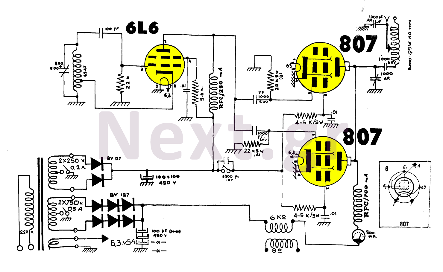
The construction utilizing two 807 tubes is robust and well-known for its performance. This design features high upward voltage and independent coupling on the output tubes, resulting in an increase in output power by several watts. While the output...
Warning: include(partials/cookie-banner.php): Failed to open stream: Permission denied in /var/www/html/nextgr/view-circuit.php on line 713
Warning: include(): Failed opening 'partials/cookie-banner.php' for inclusion (include_path='.:/usr/share/php') in /var/www/html/nextgr/view-circuit.php on line 713