
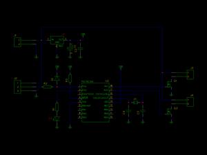
Multiple switches on Arduino analog pin schematic

The circuit design involves connecting a 5-way joystick or button module to an Arduino microcontroller through a single analog input pin. The joystick's multiple states are represented by varying voltage levels, which correspond to the different positions of the joystick. This design simplifies the input method, allowing for multiple states to be detected without requiring multiple digital pins.
In this configuration, each state of the joystick generates a specific voltage: 0V when released, and increasing voltages (1V to 5V) as the joystick is moved in different directions. The addition of a 1 MΩ resistor (R7) serves as a pull-down resistor, ensuring that the voltage is stable when all switches are open. This configuration is particularly useful in applications where power consumption needs to be minimized, such as in battery-operated devices, although in this case, the design does not prioritize battery operation.
For further refinement, the internal pull-up resistors available on the Arduino can be enabled. This alternative approach eliminates the need for external resistors by using the microcontroller's built-in features to maintain a defined voltage level when switches are not engaged. This can enhance reliability and reduce component count in the circuit.
Overall, the implementation of a 5-way joystick connected to a single analog pin provides an efficient solution for input handling in various electronic projects, facilitating user interaction while conserving resources.Connect a 5 way button/joystick to an Arduino using a single analog pin and wanted to quickly simulate it to verify my calculations before I went and soldered everything. The voltages for the six states are 0, 1, 2, 3, 4, 5. The 4V being shown in the photo is because one of the switches is pressed. I solved the problem of the all switches open state voltage by adding in the 1Mohm R7, which was okay for me since
I wasn`t making something battery operated. Some people prefer to turn on the internal pull-up on the chip.
Related Circuits

This circuit is a resonant twin-T filter. Its purpose is to provide a reasonable imitation of a low-pass response, which it achieves effectively. The schematic illustrates two variations: one with self-oscillation and one without. The version built includes oscillation....
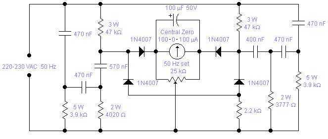
Mains frequency is pretty stable and it is unlikely that you have to measure it but if you have an emergency generator you might find this circuit useful as it will give an indication whether the generator is running...

The F-V input frequency is locked to the V-F output because the LTCIG43's clock is common to both sections. The F-V's reference is used as one input of the multiplier, while the V-F provides the other. To calibrate, short...

The Ultra Fast Battery Charger for Nickel-Cadmium (NiCad) battery cells is designed to efficiently charge NiCad batteries. This charger, referred to as the Ultra Fast NiCad Battery Charger, is capable of rapidly filling NiCad battery cells. The charger is...
As circuit power supply voltages decrease and green energy trends gain popularity, designers should re-evaluate circuits that continuously consume power to reduce overall system power consumption. One such circuit is the "normally-ON" circuit, which can now be redesigned with...
To quickly determine if a remote control transmitter is functioning properly, a remote control detector can be utilized. If the remote control transmitter is operational, the detector will emit an audible alarm signal. This detector is capable of assessing...