
NE612 heterodyne detector
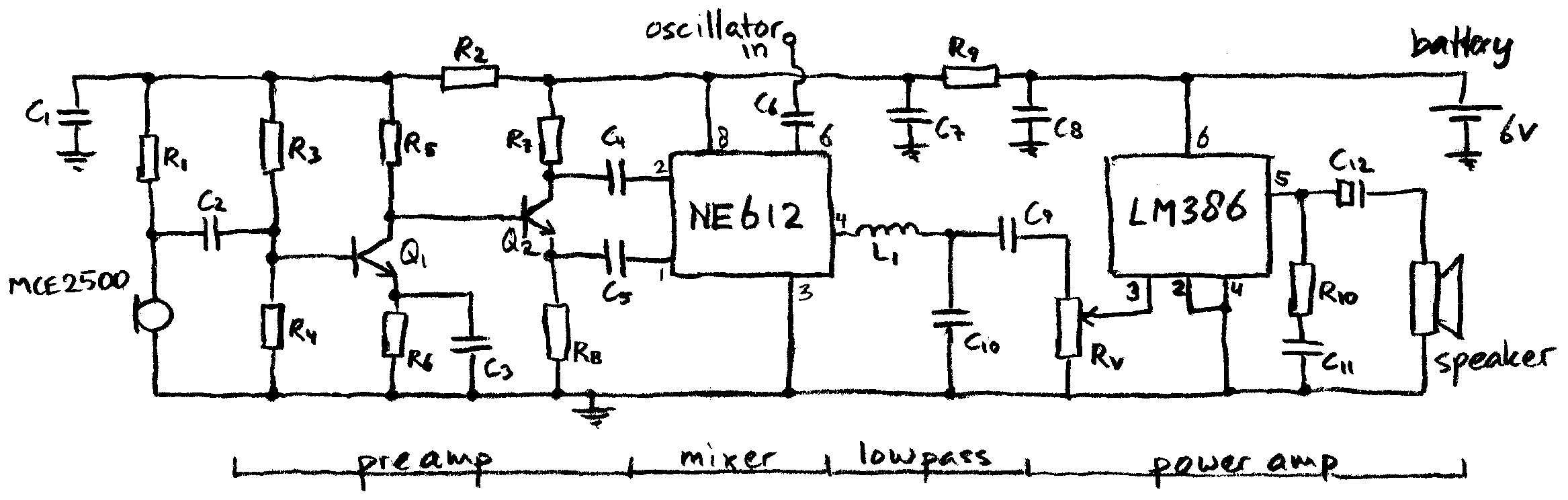
When the frequency is set to about 35 kHz, it is even possible to hear the 32, 768 Hz vibrating crystal inside an electronic wrist watch held close to the microphone! The signal from the MCE-2500 electret microphone is amplified by the pre-amp, then it is mixed with a square wave from the variable oscillator and finally low-pass filtered and amplified for headphones.
The microphone is a special small type of electret. It is able to pick up sounds up to at least 60 kHz and possibly even further although the signal-to-noise ratio gets worse with higher frequency. My microphone draws about 0. 45 mA, relatively independent of supply voltage. By feeding it with a 4k7 resistor, its DC voltage sits around 2. 1 volts lower than the battery voltage. Because of the current-source behaviour of the microphone, the 4k7 resistor will dominate the source impedance.
The amplifying element is the leftmost transistor, which is a low-noise type BC550C. The `C` indicates a high current gain, which is desirable because it means that the base current will be low. In the datasheet a low noise setpoint has been given of 200 uA collector current for a source impedance of 2k.
Since in this case we have a higher source impedance of 4k7 ohms, a lower collector current of 100 uA has been chosen. The capacitor from emitter to ground has been chosen to give a rising gain vs. frequency characteristic. Maximum gain (about 50) is reached at about 100 kHz. The rightmost transistor is used as an emitter-follower to buffer the signal from the amplifier and provide a low output impedance to the mixer.
A 4046 PLL IC is being used as a squarewave oscillator. This IC is very convenient, because of its linear relationship between voltage and frequency and its low power consumption. The resistor and capacitor values have been chosen such that a frequency can be set from 10 kHz to approx.
120 kHz. The signal of the VCO in the 4046 is buffered by feeding it into the internal phase detector. At pin 2 it exits the 4046 and is fed into a resistive divider to give a signal of about 260 mV amplitude, suitable for input into the NE612 mixer. A NE612 is a mixer (multiplier), with a low current consumption of about 2 mA. Besides multiplying, it also provides a conversion gain of about 7. Input coupling is done with 10 nF capacitors, which means that frequencies below 10 kHz are attenuated.
By multiplying the bat signal with the oscillator signal, an output signal containing frequencies of the sum and difference of the input frequencies, are generated. After being mixed in the NE612, the signal passes through a simple first-order low-pass filter with a cut-off of about 3.
5 kHz which filters out the sum frequencies and passes the difference frequencies. The volume of the output is set by the volume potmeter, which should be a logarithmic potmeter. Finally the signal is amplified (20 times) by the LM386 audio amplifier and can be used to directly drive a pair of headphones. (Perhaps a small loudspeaker can be connected instead of headphones, by connecting a 1 uF capacitor between pins 1 and 8 of the LM386to boost the gain, but I have yet to try that).
Components values aren`t very critical, however I used metal film 1% resistors for the input stage for good accuracy and low noise. For the 47uF capacitors, I used electrolytics (watch the polarity !). The addition of a single resistor to the output stage of the preamp makes it into a balanced circuit.
Problems with feedback will be smaller while the total gain of the bat detector is doubled. This improvement was inspired by the high-pass filter on my preamps page. A simple LCR circuit in a slightly different configuration instead of a RC makes the low-pass filter sharper and steeper. The number of components is still the same. This consists of a 50 nF capacitor and a 10 ohm resistor right at the output of the LM386 power amp (as suggested in the LM386 datasheet).
Although the circuit may seem to work without these components, they can prevent high frequency oscillation. A 47 uF output capacitor (as currently used) results in a 432 Hz cut-off, which is a bit high. Choosing a larger value capacitor (like 250 uF as shown in the datasheet) gives a better low-frequency response.
The oscillator from the CMOS 4046 is relatively sensitive to voltage variations on its supply pin, resulting in a varying frequency. Also the waveform is a square wave, which is relatively rich in unwanted harmonics. A triangle wave oscillator is much lower in harmonics and can be made rather insensitive to voltage variations.
However I`m having trouble making it oscillate well at frequencies higher than 100 kHz. See also the triangle wave circuit at the mixer and oscillators page. This is a classic opamp relaxation oscillator. The amplitude of oscillation is set by resistors R1, R2 and R3. In this case they are set to produce a little less than 1/20th of the supply voltage, about 200 mV. Components C1, R4 (=potmeter) and R5 (=trimpotmeter) further set the frequency of oscillation. To set the upper frequency of the oscillator, put R4 in its lowest setting (=highest frequency) and adjust R5 for the desired upper frequency. The lower frequency of this oscillator is fixed at about 20 kHz. The main difference is the use of a voltage regulator to get a stable 5 Volt supply for the pre-amplifier and mixer.
The 5V regulator can be a simple 7805 regulator or perhaps a more advanced low-dropout low quiescent current regulator like the TL750L05. All of the other parts of the circuit use this 5V, except for the power amplifier which still runs from the raw voltage from a 9V block battery.
For the oscillator a 7555 chip is used. The 7555 is a CMOS version of the well-known 555 timer chip. I`m using this because it is a very simple circuit that draws little current and uses just a small number of components. 🔗 External reference
Related Circuits
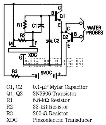
The moisture detector utilizes two transistors and a piezoelectric transducer to emit an alarm tone when water is detected. Transistor Q1 functions as a crystal-controlled oscillator, employing a portion of the piezoelectric transducer XDC, which consists of two piezoelectric...
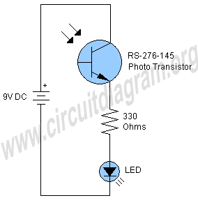
This is a straightforward infrared detector circuit designed to detect infrared light. The circuit comprises only three components: an RS-276-145 photo transistor, a 330-ohm resistor, and a general-purpose LED (Light Emitting Diode). When the photo transistor receives infrared light...
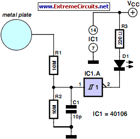
This simple circuit can be used to activate various devices, such as microcontrollers, relays, secret alarms, or even to turn on LED1, which illuminates as long as a metal plate is touched. The circuit consists of a voltage divider...
The PTB78560x is a series of 30 W rated isolated DC/DC converters designed to operate from a standard 24 V or 48 V telecom central office (CO) supply. Housed in a 12 package, each model features a wide adjustable...
The power drain is approximately 150 mA. IC1 provides a regulated 5-volt supply for the filament heater of the sensor. The gas-sensitive element is connected as one arm of a resistance bridge consisting of R4, R7, R8, and the...
The GLMDPCB motion detector board is a double-sided etched, screened, and drilled printed circuit board designed for the GLMDA motion detector circuit illustrated in the schematic below. The circuit can be constructed in its entirety or in part. For...