
infrared detector circuit
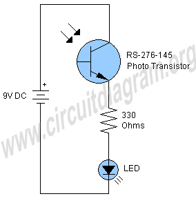
The infrared detector circuit operates on the principle of light detection using a photo transistor, which is sensitive to infrared radiation. The RS-276-145 photo transistor is the critical component that responds to infrared light by changing its conductivity. When infrared light strikes the surface of the photo transistor, it generates a small current, which is then amplified by the transistor.
The circuit configuration is simple: the photo transistor is connected in series with a 330-ohm resistor and the LED. The LED is connected in parallel to the photo transistor. When the photo transistor detects infrared light, it allows current to flow through the circuit, causing the LED to illuminate. The 330-ohm resistor serves to limit the current flowing through the LED, preventing it from burning out due to excessive current.
This type of circuit can be used in various applications, including remote control systems, motion detection, and safety alarms. The simplicity of the circuit design allows for easy integration into larger systems or standalone applications. Additionally, the use of a general-purpose LED makes it cost-effective and readily available for various projects.
For optimal performance, the circuit can be adjusted by changing the resistor value or using different photo transistors, depending on the specific requirements of the application. Proper placement of the components is also essential to ensure that the photo transistor has a clear line of sight to the infrared light source, maximizing detection efficiency.Here is a very simple infrared detector circuit which can be used to detect infrared light. The circuit is consist of only three components a RS-276-145 photo transistor, 330 Ohms resistor and a general purpose LED (Light Emitting Diode). When the photo transistor will receive any IR on its surface it will 🔗 External reference
Related Circuits

This is the design of a bias current compensation circuit. This circuit can operate with medium wattage source resistances while maintaining a minimal increase in the equivalent offset voltage. It is based on the LM11 operational amplifier. The circuit...

This circuit consists of two main components: a battery charger that provides a fixed output voltage of 5V DC, and a regulated power supply that allows for an adjustable output voltage ranging from 2 to 9 volts. The circuit design...
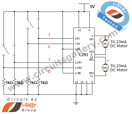
How can a DC motor be rotated in clockwise and counterclockwise directions? This is a common question posed by many robotics beginners. DC motor driver circuits are essential components in robotics workshops. The L293D IC is frequently utilized for...

In this laboratory experiment, the objective is to design the frequency-determining network for a 1 kHz sinusoidal oscillator. The specified values are as follows: Capacitance = 100 nF and Resistance = 1520 ohms. The output voltage waveform of the...

NOR gates A and B create a low-frequency oscillator that activates when the CDS cell, in dark conditions, presents a logic zero to one input of NOR gate A. This low-frequency oscillator, operating at 10 Hz, enables a high-frequency...

This is a simple passive headphone distribution box that functions effectively. It has been utilized in various recording studios and constructed for multiple users. The absence of active components ensures minimal failure risk and a quick assembly process. The...