
Ne7555 Timer For Light Sensitive Alarm Sensor
The NE555 timer is a versatile integrated circuit widely utilized in various timing, delay, pulse generation, and oscillator applications. In this specific configuration, the NE555 timer operates as a monostable multivibrator, which triggers an alarm when a light interruption is detected.
The circuit typically consists of a light-dependent resistor (LDR) that serves as the primary sensor. The LDR changes its resistance based on the intensity of the ambient light. When a sudden shadow or a decrease in light intensity occurs, the resistance of the LDR increases, causing a voltage drop across it. This change is detected by the NE555 timer, which is configured to respond to the threshold voltage at its trigger pin.
The circuit may include a resistor-capacitor (RC) network connected to the NE555 timer, which determines the timing duration of the alarm. The output from the timer can be connected to a relay or a transistor to activate an alarm or any other output device, such as a buzzer or LED indicator.
Power supply considerations for the circuit are essential, as the NE555 timer typically operates within a voltage range of 4.5V to 15V. Proper decoupling capacitors should be placed near the power supply pins of the IC to ensure stable operation.
Overall, this light-sensitive alarm sensor circuit utilizing the NE555 timer is an effective solution for applications requiring automatic detection of light changes, providing an audible or visual alert in response to sudden shadows or light interruptions.This circuit shows about Ne7555 Timer For Light Sensitive Alarm Sensor Circuit Diagram. Features: detects a sudden shadow falling on the .. 🔗 External reference
Related Circuits
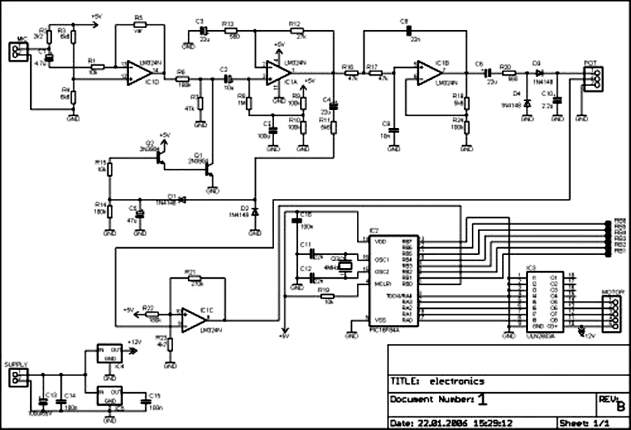
External circuit converts bass beat of music into pulses. The motor is controlled by them. If there's bass beat recognized then the motor rotates one direction (in full stepping) for a predefined time then stops. If the second beat...
This is a programmable clock timer circuit that utilizes individual LEDs to signify hours and minutes. Twelve LEDs can be arranged in a circular formation to represent the 12 hours of a clock face, while an additional 12 LEDs...
This circuit provides a visual 9-second delay using a 7-segment digital readout LED. When the switch is closed, the CD4010 up/down counter is preset to 9, and the 555 timer is disabled, holding the output high. When the switch...
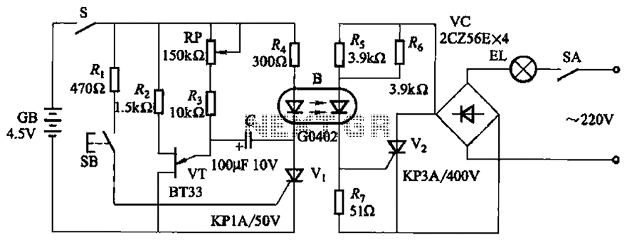
The circuit illustrated in Figure 2-48 consists of two configurations. Configuration 2-48 (a) operates using a 4.5V battery, while configuration 2-48 (b) employs AC capacitors to reduce the voltage supply. In configuration 2-48 (a), the delay time is influenced...
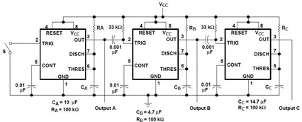
A sequential timer circuit device is utilized in various applications for initializing conditions during start-up or for activating test signals in sequences, such as in test equipment devices. The circuit diagram below illustrates a sequencer circuit with potential applications...
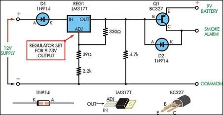
Although smoke alarms are relatively inexpensive devices, the cost of 9V batteries can quickly surpass their initial purchase price. Additionally, the annoyance of intermittent beeping from the alarm as the battery nears the end of its life can be...
Warning: include(partials/cookie-banner.php): Failed to open stream: Permission denied in /var/www/html/nextgr/view-circuit.php on line 713
Warning: include(): Failed opening 'partials/cookie-banner.php' for inclusion (include_path='.:/usr/share/php') in /var/www/html/nextgr/view-circuit.php on line 713