
9 Second Digital Readout Countdown Timer
The described circuit functions as a visual timer employing a combination of a CD4010 up/down counter, a 555 timer, and a CD4511 BCD to 7-segment decoder. The operation begins when the switch is closed, which sets the counter to its maximum preset value of 9. At this point, the 555 timer is disabled, preventing any clock signal from decrementing the counter. Upon opening the switch, the timer initiates a clock pulse approximately every second, causing the counter to decrement sequentially from 9 down to 0.
The transition to a zero count triggers the carry-out signal at pin 7, which activates a 12-volt relay. This relay serves a dual purpose: it halts the clock signal by sending a low signal to the reset line (pin 4) and remains energized until the switch is closed again. This design allows for a reset of the counter back to its initial state of 9, effectively restarting the timing cycle.
The clock pulse duration can be fine-tuned by adjusting the resistor connected to pin 3 of the 555 timer, providing flexibility in the timing application. The CD4510 counter is versatile, allowing for presetting to any value between 0 and 9 via its preset inputs (pins 4, 12, 13, and 3) and can be reset to zero through the reset line (pin 9). The counting direction is dictated by the UP/DOWN input (pin 10), with a high signal indicating an upward count and a low signal indicating a downward count.
The CD4511 decoder enhances the circuit by converting the BCD output from the counter into a format suitable for driving a 7-segment display. It can source sufficient current to illuminate the display directly, with the latch-enable, lamp-test, and blanking features allowing for additional control over the visual output. The requirement for a common cathode LED display ensures compatibility with the positive voltage needed for segment illumination.
This circuit is suitable for applications requiring a simple visual timer, such as in educational projects, hobby electronics, or basic timing functions in larger systems. Its modular design allows for easy adjustments and modifications, making it an excellent choice for experimentation and learning in electronics.This circuit provides a visual 9 second delay using a 7 segment digital readout LED. When the switch is closed, the CD4010 up/down counter is preset to 9 and the 555 timer is disabled with the output held high. When the switch is opened, the timer produces an approximate 1 second clock signal, decrementing the counter until the 0 count is reached.
When the zero count is reached, the `carry out` signal at pin 7 of the counter moves low, energizing the 12 volt relay and stopping the clock with a low signal on the reset line (pin 4). The relay will remain energized until the switch is again closed, resetting the counter to 9. The 1 second clock signal from the 555 timer can be adjusted slightly longer or shorter by increasing or decreasing the resistor value at pin 3 of the timer.
The CD4510 is a CMOS Presettable BCD Up/Down counter which can be preset to any number between 0 and 9 with a high level on the PRESET ENABLE line, (pin 1) or reset to 0 with a high level on the RESET line (pin 9). Inputs for presetting the counter (P1, P2, P3, P4) are on pins (4, 12, 13, 3) respectively. The counter advances up or down on each positive-going clock transition (pin 15) and the counting direction (up or down) is controlled by the logic level on the UP/DOWN input (pin 10, high=up, low=down).
The CARRY-IN signal (pin 5) disables the counter with a high logic level. The CD4511 is a CMOS BCD to 7 segment latch decoder capable of sourcing up to 25 mA which allows it to drive LEDs and other displays directly. A LATCH-ENABLE line (pin 5, active low) stores data from the BCD input lines. A LAMP-TEST input (pin 3, active low) can be used to illuminate all 7 segments, and a BLANKING input (pin 4, active low) can be used to turn all segments off.
The LED display must be a common cathode type so that the segments are illuminated with a positive voltage on their respective connections. 🔗 External reference
Related Circuits

The Kelvin scale version reads from 0 to 1999 K theoretically, and from 223 K to 473 K actually. The 26 kΩ resistor brings the input within the ICL7106 common-mode voltage range; two general-purpose silicon diodes or an LED...
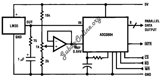
This is a design for a temperature-to-digital converter circuit that is controlled by the LM35 integrated circuit. The LM35 is a precision integrated circuit temperature sensor, whose output voltage is linearly proportional to the Celsius temperature. The circuit utilizes the...
I had a Basic Stamp project that needed to measure a nominal 12 volt battery, and I wanted a simple solution. This is the simplest I could come up with. The 555 timer will put out positive pulses. The...

It may be easy to find a precision voltage reference for your application; however, a programmable precision reference is another matter. The circuit in Figure 1 yields a precision reference with an LSB of 62.5 µV. The circuit is...
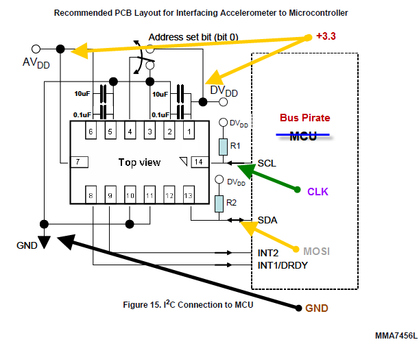
The Bus Pirate is an effective tool for exploring new chips with a PC, eliminating the need for integration into a microcontroller project. Upon receiving the unit, testing it with the MMA7456L accelerometer featuring an I2C/SPI interface from Freescale...
The Clock Controller was designed to be an exemplary of using 'C' language to control timer0 interrupt, 7-segment LED and keypad scanning. It provides 1-bit sink current driving output, for driving a relay, opto-triac, say. Many projects requiring 7-segment...
Warning: include(partials/cookie-banner.php): Failed to open stream: Permission denied in /var/www/html/nextgr/view-circuit.php on line 713
Warning: include(): Failed opening 'partials/cookie-banner.php' for inclusion (include_path='.:/usr/share/php') in /var/www/html/nextgr/view-circuit.php on line 713