
New Knight Rider LED Board

The Left and Right LEDs are connected in series, and if this circuit is used on a 12-volt system, a person could connect 2 LEDs for each LED shown. Additionally, the LEDs are mounted on the circuit board, but they can be wired off-board if desired.
1) There is a 1K pot that adjusts the voltage input to the LM3914. 2) There is a 5K pot that adjusts the output voltage of the sawtooth oscillator. 3) There is a 250K pot to set the frequency as desired. 4) Additionally, there is a connection point between Pin 9 of the LM3914. Joining these together creates a bar display. 5) Substituting an LM3915 or an LM3916 will create a non-linear effect in the lights.
The circuit utilizes a TL082 or TL072 operational amplifier to generate an adjustable sawtooth waveform. The choice of operational amplifier is flexible, as both components provide suitable performance for this application. The sawtooth generator can also produce a square wave output; however, this feature is not utilized in the current configuration.
In this design, the left and right LEDs are connected in series, allowing for visual output that can be modified based on the input voltage. When operating in a 12-volt system, it is possible to parallel additional LEDs, enhancing the brightness and visual impact of the circuit. The physical arrangement of the LEDs can be on the circuit board or off-board, providing flexibility in design and implementation.
The circuit includes three adjustable potentiometers: a 1KΩ potentiometer for fine-tuning the voltage input to the LM3914 display driver, a 5KΩ potentiometer for adjusting the output voltage of the sawtooth oscillator, and a 250KΩ potentiometer to control the frequency of the sawtooth waveform. These components allow for precise control over the circuit's performance, enabling users to customize the output to meet specific requirements.
Furthermore, there is a critical connection point at Pin 9 of the LM3914, which, when joined with other points in the circuit, facilitates the creation of a bar graph display. This feature enhances the visual representation of the output signal, providing an intuitive indication of the sawtooth waveform's characteristics.
For applications requiring different visual effects, substituting the LM3914 with an LM3915 or LM3916 can introduce a non-linear response in the LED display. This modification can be beneficial for applications where varying intensity levels are desired, further expanding the versatility of the circuit.The TL082 (Or a TL072 also is OK) Creates an Adjustable Sawtooth Generator. (It also has a Square wave Output, but it isn`t used here.) The Left and Right LED`s are Connected in Series and if this circuit is used on a 12 volt system, and if a person wanted to they could connect 2 LED`s for each LED Shown. Additionally I show the LED`s Mounted on the Circuit Board, But they can be wired OFF Board if So Desired.
1) There is a 1K Pot that adjust the Voltage input to the LM3914. 2) There is a 5K pot that adjust the Output voltage of the Sawtooth Oscillator. 3) There is a 250K Pot to set the Frequency as Desired. 4) Additionally there is a Connection point between Pin 9 of the LM3914. Joining these together to creates a Bar Display. 5) Substituting an LM3915 or an LM3916 will create a Non-Linear Effect in the Lights. 🔗 External reference
Related Circuits
This circuit utilizes small switching transistors, with a maximum motor drive current limited to approximately 250 mA at 5V. Testing has been conducted across a voltage range from 3V to 21V, and with certain component modifications, it may be...
Savings on electricity bills can be achieved by utilizing alternative power sources. The photovoltaic module or solar panel described here has a power output of 5 watts, providing 16.5V under full sunlight conditions, with a current delivery of 300-350...
Light emitting diodes are advantageous due to their smaller size, low current consumption and catchy colours they emit. Here is a running message display circuit wherein the letters formed by LED arrangement light up progressively. Once all the letters...
Twelve LEDs can be arranged in a circle to represent the twelve hours of a clock face, while an additional twelve LEDs can be arranged in an outer circle to indicate five-minute intervals within the hour. Four additional LEDs...
The circuit below demonstrates how to power one or two LEDs from a 120-volt AC line. It utilizes a capacitor to reduce the voltage and a small resistor to limit the inrush current. As the capacitor needs to allow...
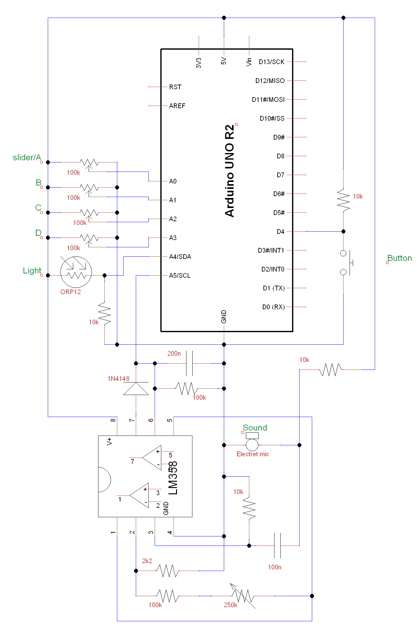
A circuit and Arduino code are designed to emulate a ScratchBoard approximately. The setup includes sound, light, a button, and four sliders, but it is not a direct replacement. It is important to change the COM ports in the...