
28 LED Clock Timer
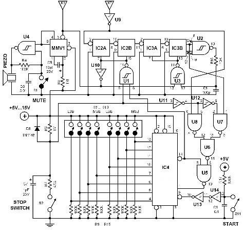
The described circuit represents a comprehensive timekeeping system that efficiently utilizes a combination of digital logic components and discrete elements to create a functional clock with additional features for time intervals. The dual layer of LEDs provides a visual representation of both hours and finer minute increments, allowing for precise time indication. The use of a center-tapped transformer ensures stable power delivery, while the Zener diode regulates the voltage to protect sensitive components. The integration of counters and decoders facilitates accurate counting and display of time, with the ability to set specific intervals for relay control. The design also incorporates manual override capabilities, enhancing usability and flexibility for various applications. Overall, the circuit exemplifies a well-structured approach to digital timekeeping, incorporating both functionality and user interaction.12 LEDs can be arranged in a circle to represent the 12 hours of a clock face and an additional 12 LEDs can be arranged in an outer circle to indicate 5 minute intervals within the hour. 4 additional LEDs are used to indicate 1 to 4 minutes of time within each 5 minute interval. The circuit is powered from a small 12. 6 volt center tapped line transformer and the 60 cycle line frequency is used for the time base. The transformer is connected in a full wave, center tapped configuration which produces about 8. 5 volts unregulated DC. A 47 ohm resistor and 5. 1 volt, 1 watt zener regulate the supply for the 74HCT circuits. A 14 stage 74HCT4020 binary counter and two NAND gates are used to divide the line frequency by 3600 producing a one minute pulse which is used to reset the counter and advance the 4017 decade counter. The decade counter counts the minutes from 0 to 4 and resets on the fifth count or every 5 minutes which advances one section of a dual 4 bit binary counter (74HCT393).
The 4 bits of this counter are then decoded into one of 12 outputs by two 74HCT138 (3 line to 8 line) decoder circuits. The most significant bit is used in conjunction with an inverter to select the appropriate decoder. During the first eight counts, the low state of the MSB is inverted to supply a high level to enable the decoder that drives the first 8 LEDs.
During counts 9 to 12, the MSB will be high and will select the decoder that drives the remaining 4 LEDs while disabling the other decoder. The decoded outputs are low when selected and the 12 LEDs are connected common anode with a 330 ohm current limiting resistor to the +5 volt supply.
The 5th output of the second decoder (pin 11) is used to reset the binary counter so that it counts to 11 and then resets to zero on the 12th count. A high reset level is required for the 393 counters, so the low output from the last decoder stage (pin 11) is inverted with one section of a 74HCT14 hex Schmitt trigger inverter circuit.
A 10K resistor and 0. 1uF cap are used to extend the reset time, ensuring the counter receives a reset signal which is much longer than the minimum time required. The reset signal is also connected to the clock input (pin 13) of the second 4 bit counter (1/2 74HCT393) which advances the hour LEDs and resets on the 12th hour in a similar manner.
Setting the correct time is accomplished with two manual push buttons which feed the Q4 stage (pin 7) of the 4020 counter to the minute and hour reset circuits which advance the counters at 3. 75 counts per second. A slower rate can be obtained by using the Q5 or Q6 stages. For test purposes, you can use Q1 (pin 9) which will advance the minutes at 30 per second. The time interval circuit (shown below the clock) consists of a SET/RESET flipflop made from the two remaining NAND gates (74HCT00).
The desired time interval is programmed by connecting the anodes of the six diodes labeled start, stop and AM/PM to the appropriate decoder outputs. For example, to turn the relay on at 7:05AM and turn it off at 8:05AM, you would connect one of the diodes from the start section to the cathode of the LED that represents 7 hours, the second diode to the LED cathode that represents 5 minutes and the third diode to the AM line of the CD4013.
The stop time is programmed in the same manner. Two additional push buttons are used to manually open and close the relay. The low start and stop signals at the common cathode connections are capacitively coupled to the NAND gates so that the manual push buttons can override the 5 minute time duration. That way, you can immediately reset the relay without waiting 5 minutes for the start signal to go away.
The two power supply rectifier diodes are 1N400X variety and the switching diodes are 1N914 or 4148s but any general purpose diodes can be used. 0. 1 u 🔗 External reference
Related Circuits
The time interval of this circuit can be varied digitally through the DIP switches. The time code must be set in BCD form. A 120 Hz signal generated by doubling the line frequency is used as the time reference....
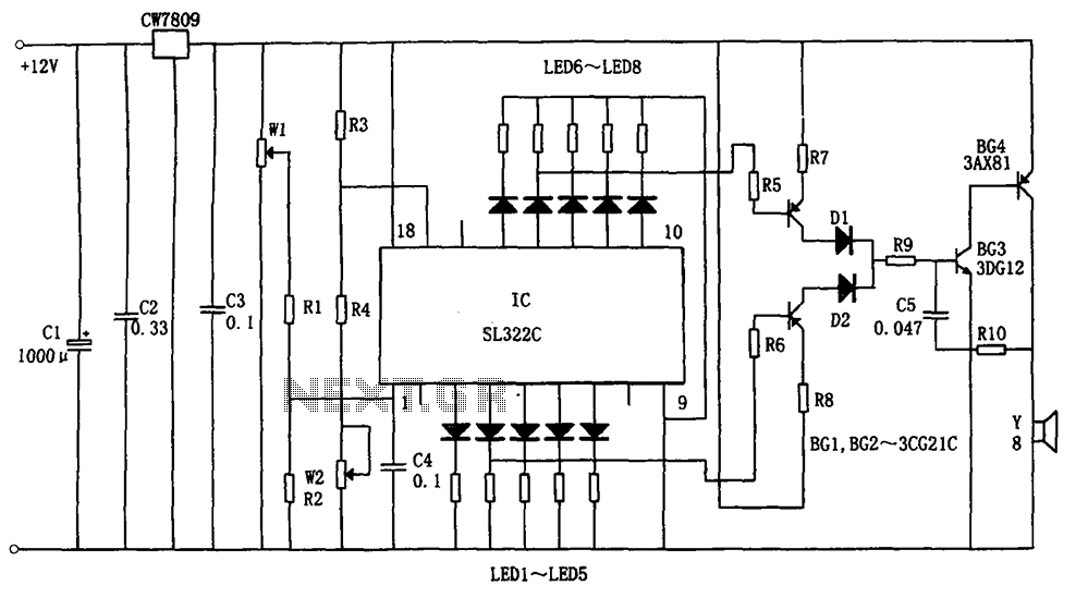
The circuit illustrated in the figure is a hydraulic oil level alarm system for automotive applications. It consists of a light-emitting diode (LED) driver, the SL322C integrated circuit (IC), a voltage regulator circuit (CW7809), and hydraulic oil level sensors...
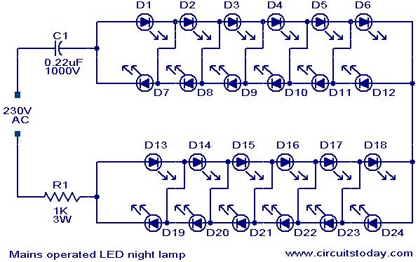
This is a simple and effective LED-based night lamp circuit that can be powered directly from a 230V mains supply. The circuit uses a total of 24 white LEDs and produces an output of approximately 15W. The resistor R1...
Are you unfamiliar with the basics of electronics? An online store has recently opened, offering four excellent books on basic electronics for sale. Reviews of these books are available, and purchases can be made as desired. These books are...
The goal was to create a compact flashlight that could be held in the mouth, easily stored in a pocket, and positioned on a surface to project light upwards. The budget was set at approximately $15, which was significantly...
A circuit of measurement of level based on a typical application of National. The circuit round the IC1 makes input adaptation and amplification with the trimmer TR1 [GAIN]. The circuit round the IC2 makes half-wave rectification of acoustic signal....
Warning: include(partials/cookie-banner.php): Failed to open stream: Permission denied in /var/www/html/nextgr/view-circuit.php on line 713
Warning: include(): Failed opening 'partials/cookie-banner.php' for inclusion (include_path='.:/usr/share/php') in /var/www/html/nextgr/view-circuit.php on line 713