
Night light Wake up Alarm Combo circuit
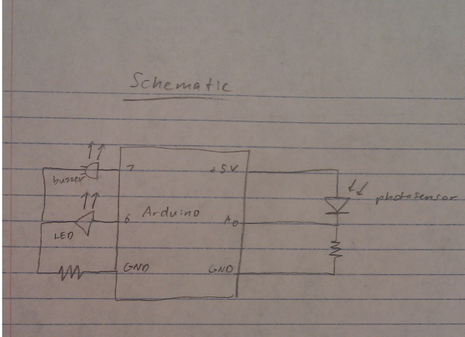
This project involves the integration of a nightlight and alarm system, designed to function based on ambient light conditions. The circuit comprises six light-emitting diodes (LEDs) and a buzzer, which are controlled by a microcontroller, typically an Arduino. The LEDs serve as the primary light source, illuminating the area when the photosensor detects low light levels, typically defined by a threshold value set in the software.
The photosensor, connected to an analog input pin, continuously monitors ambient light levels. When the light level falls below a predetermined threshold (DARKNESS), the microcontroller activates the LEDs, providing illumination. As the ambient light increases above another threshold (LIGHT), the microcontroller deactivates the LEDs and triggers the buzzer to play a melody, signaling the transition from dark to light.
The circuit design includes the following components:
- **Microcontroller**: Acts as the central processing unit, executing the programmed logic to control the LEDs and buzzer based on inputs from the photosensor.
- **Photosensor**: A light-dependent resistor (LDR) that changes resistance based on light exposure, providing the necessary input to the microcontroller.
- **LEDs**: Six LEDs arranged in a line, connected to digital output pins of the microcontroller. Each LED can be turned on or off based on the light conditions.
- **Buzzer**: A piezoelectric speaker connected to a digital output pin, programmed to emit sound when the ambient light increases.
The software component includes defining constants for light thresholds, pin assignments, and musical notes. The program initializes the LED pins as outputs and the photosensor pin as an input. In the main loop, the program reads the value from the photosensor and compares it to the defined thresholds, activating or deactivating the LEDs and the buzzer accordingly.
For enhanced functionality, the system could be modified to include a potentiometer that allows users to adjust the sensitivity of the photosensor, giving them control over when the nightlight activates. Additionally, a snooze button could be implemented to temporarily silence the alarm, allowing for a more customizable user experience.
Overall, this nightlight and alarm system combines practical functionality with user-friendly features, providing comfort and convenience in a simple yet effective design.We chose to build a nightlight combined with a wake-up alarm. Our nightlight features not one, not two, not three, not four, not five, but SIX ” yes, SIX! ” LEDs that turn on when a photosensor detects a decreased amount of ambient light. Not only that, but we also included a buzzer that plays a friendly tune whenever our system detects that a mbient light levels have increased again. The purpose of this system is twofold: First, by providing light when its surroundings are dark, it reassures and comforts those who are afraid of the dark. Second, it audibly announces the return of light to those who might have closed their eyes or otherwise lost sensory input (e.
g. , the sleeping or suddenly blind). Our system is a smashing success, as it correctly lights up in the dark and plays a tune, as specified. We particularly liked the reassuring charm of the system`s adorable lights and catchy jingle. A possible improvement would be implementing a continuous alarm that the user can turn off (for example, by turning a potentiometer) ” more like a typical alarm clock.
We could even include a snooze button. 1. Set up the LEDs in a line on a bread board next to the photoresistor. Place the speaker across the cen ter divider of the other bread board. You may find it help ful to con nect ground and +5V to the power rails of the bread board for the fol low ing steps. 3. Check the val ues out put by the photoresistor using the ser ial mon i tor and the Serial. println() func tion. In the code, change the PHOTO_MAX and PHOTO_MIN val ues as appropriate. /* Authors: jasnyder, cwhetung, menewman, jyltwo Date: 2/25/2013 COS 436 Lab L1: The Nightlight Alarm The nightlight alarm: lights turn on when it`s dark, and when it gets bright again, the lights turn off and an alarm goes off to wake you up!
*/ #include "pitches. h" const int FALSE = 0; const int TRUE = 1; // Input / Output Constants const int PHOTO_MIN = 100; // set me as appropriate! const int PHOTO_MAX = 1023; // set me as appropriate! const int DARKNESS = 500; // set me as appropriate! const int LIGHT = 700; // set me as appropriate! // Musical Constants const int NOTE_DELAY = 300; // (ms) const int NOTE_DUR = 250; // Pin Connection Constants const int photo = A0; const int red1 = 5; const int red2 = 3; const int red3 = 1; const int yellow1 = 4; const int yellow2 = 2; const int yellow3 = 0; const int speaker = 8; // Variables boolean islight = false; int photovalue = 0; // value returned by photo sensor // Set internal pull-ups for output on LED pins void setup() { pinMode(red1, OUTPUT); pinMode(red2, OUTPUT); pinMode(red3, OUTPUT); pinMode(y< DARKNESS && islight true; } } // Play a clas
🔗 External reference
Related Circuits
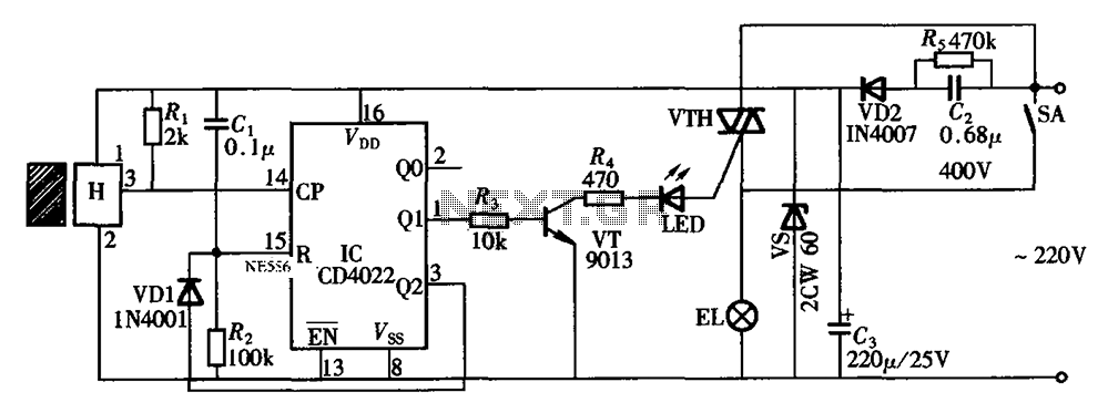
The circuit illustrated in the figure depicts an automatic bathroom light switch system. When the door is opened, the light is activated, illuminating the space. Conversely, when the door is opened again, the light turns off. The circuit comprises...

220V AC power is supplied through a VD1 to VD4 bridge rectifier and a voltage regulator circuit involving R1, R2, and VD5 components. The output provides a DC voltage of approximately 3V, which powers the manifold A. The manifold...

This is a design schematic for sensing the electromagnetic field. The circuit is built using a 741 operational amplifier (op-amp) IC. It can detect electromagnetic fields, including those from hidden wiring. A 1mH inductor is employed for sensing the...

The Vehicle Anti-Hijack Alarm No3 is designed specifically for scenarios where a hijacker forcibly removes the driver from the vehicle. If any door is opened while the ignition is on, the circuit will activate. The Vehicle Anti-Hijack Alarm No3...
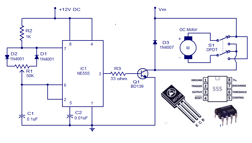
This weblog discusses electronic circuit schematics, PCB design, DIY kits, and electronic project diagrams. A simple DC motor controller circuit utilizing the NE555 timer is presented. Several DC motor speed control circuits are explored, with this being the first...
The thermistor utilized has a resistance of 15k ohms at 25 degrees Celsius and 45k ohms at 0 degrees Celsius. A suitable bead-type thermistor can be sourced from the Maplin catalogue. The inclusion of a 100k potentiometer enables this...
Warning: include(partials/cookie-banner.php): Failed to open stream: Permission denied in /var/www/html/nextgr/view-circuit.php on line 713
Warning: include(): Failed opening 'partials/cookie-banner.php' for inclusion (include_path='.:/usr/share/php') in /var/www/html/nextgr/view-circuit.php on line 713