
Automatic bathroom light switch circuit CD4022 composed
The automatic bathroom light switch circuit operates based on the detection of the door's position through a hall effect sensor. This sensor detects magnetic fields and is typically positioned near the door frame, activating the circuit when a magnet, mounted on the door, comes into proximity.
Upon door entry, the hall switch is triggered, sending a signal to the octal counter (CD4022). This counter is designed to count the number of pulses it receives, which corresponds to the door's state (open or closed). The CD4022 is a binary counter that can count up to eight states, providing a reliable method for tracking the door's position.
The pulse divider function of the CD4022 is crucial as it ensures that each opening and closing of the door results in a single pulse being sent to the Triac. The Triac acts as a switch that controls the power to the bathroom light. When the Triac receives a signal from the counter, it allows current to flow to the light fixture, illuminating the bathroom.
For the circuit to function correctly, additional components such as resistors and capacitors may be included to stabilize the operation and prevent false triggering. The design ensures that the light remains on as long as the door is open and turns off automatically when the door is closed again. This automatic control not only enhances convenience but also contributes to energy savings by preventing unnecessary light usage.
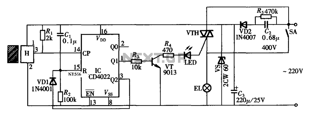
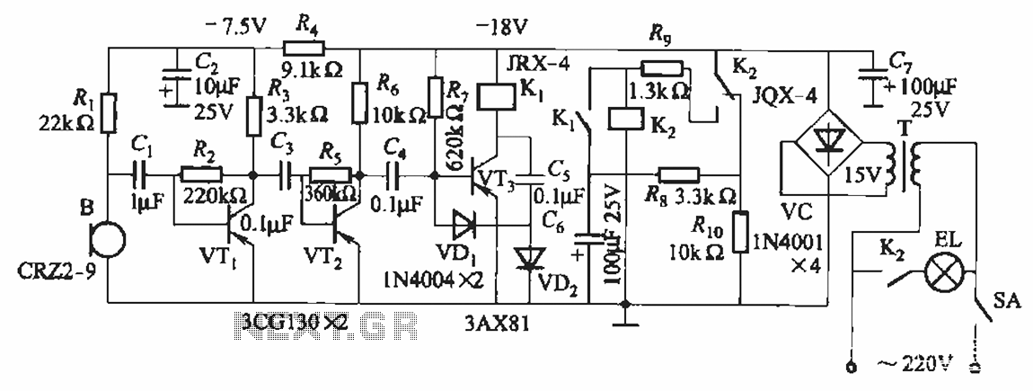
Overall, this circuit design effectively combines several electronic components to create a user-friendly and energy-efficient lighting solution for bathroom environments. As shown in FIG bathroom light switch gated automatic way, when someone enters, once the door is opened, the light switch is turned on bright lights. When the out door is opene d once again, switch off the lights off. Circuit as shown in FIG. By the Hall switch circuit, octal counting, pulse divider CD4022 and Triac VTH and other components.
Related Circuits
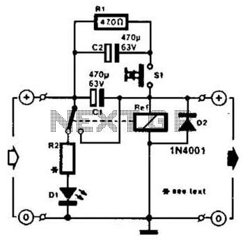
A method of adding overload protection to a power supply using a relay is shown. In each circuit, the relay must be reset by a momentary switch using a charge on capacitor C2. This prevents overload if the short...
This precise one-pulse-per-second clock is constructed using a few common components and is driven by a 50 or 60 Hertz mains supply, without any direct connection to it. It produces a beep or metronome-like click and/or a visible flash...
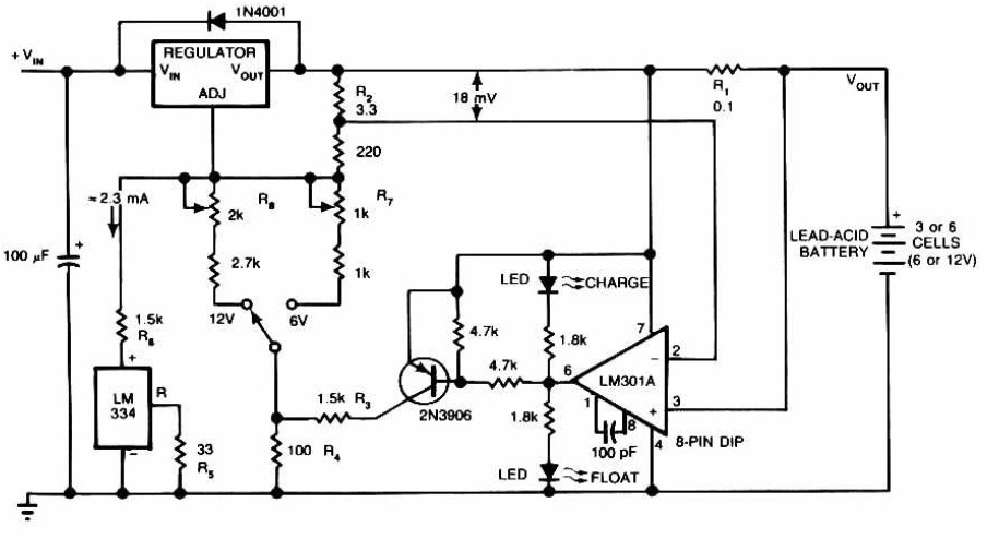
Lead-Acid Battery Charger circuit diagram. The LM301A compares the voltage drop across R1 with an 18 mV reference set by R2. The comparator's output controls the voltage regulator, forcing it to produce the lower float voltage when the battery-charging...
The circuit utilizes relay control. The voice switch operates as follows: upon the first clap, the load (lights) is activated; upon the second clap, the load (lights) is deactivated. This system can be employed to control lighting in residential...
This simple alarm timer circuit is constructed using a 4060 IC, which features an integrated oscillator known for its good stability and relatively wide frequency range. The 4060 integrated circuit (IC) serves as the core component of this alarm timer...

By adjusting one potentiometer, the output of this circuit can be varied from a positive version of the input signal, smoothly transitioning through zero output, and then to a negative version of the input. For instance, if the input...