
Nine one-way operation of the dynamic braking circuit

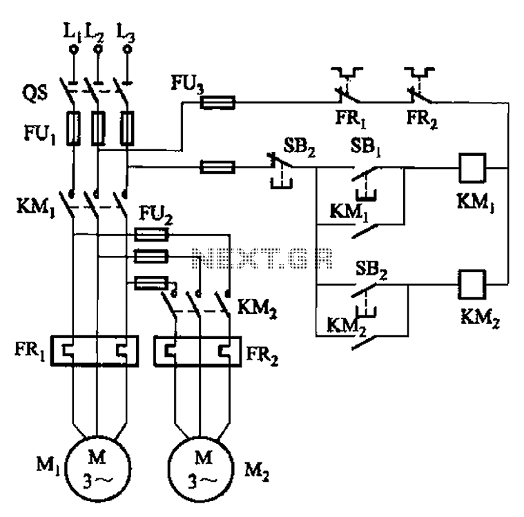
The circuit diagram in Figure 3-141 represents a control system utilizing an autotransformer for voltage regulation during motor startup and dynamic braking operations. The autotransformer serves as a variable voltage source, allowing for a smooth increase in voltage applied to the motor, thereby reducing inrush current and mechanical stress. This is particularly beneficial in applications requiring gradual acceleration.
The buck start button (SBi) initiates the startup sequence, engaging the autotransformer to provide the necessary voltage to the motor. The operation of the motor can be halted using the stop button (SBz), which interrupts the power supply.
The buck start-up time is managed by time relay KT1. This relay ensures that the voltage ramp-up is controlled over a predetermined duration, minimizing the risk of electrical and mechanical shock to the system. The specific time delay can be adjusted based on system requirements to optimize performance.
Dynamic braking is an essential feature for quickly stopping the motor and is controlled by time relay KT2. This relay offers an adjustable braking time ranging from 2 to 3 seconds, allowing for customization based on the load characteristics and operational needs. The dynamic braking function dissipates the kinetic energy of the motor, converting it to heat, which is then managed by the braking resistors in the circuit.
In summary, this circuit design effectively integrates an autotransformer for controlled voltage application during startup and employs time relays to manage both the startup and braking processes, ensuring efficient and safe operation of the motor system. Circuit shown in Figure 3-141. The line autotransformer voltage starting, dynamic braking. Figure, SBi buck start button, SBz the stop button. Buck start-up time by the time re lay KT] control. Dynamic braking time is determined by the time relay KT2 (2 ~ 3s adjustable).
Related Circuits
Short circuits or broken PCB tracks can be easily identified using a multimeter; however, this tool may yield inaccurate results when testing the efficiency of a transistor or diode unless the component is unsoldered and removed from the PCB....
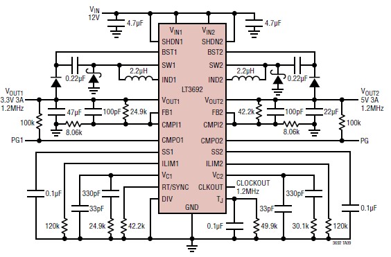
The LT3692 dual current mode PWM step-down DC-DC converter circuit, featuring two internal 3.5A switches, can be designed into a simple power supply circuit suitable for various electronic applications, such as distributed supply regulation or automotive circuits. The LT3692...
The circuit illustrated in Figure 3-83 demonstrates that the contactor KMi is activated only after it is pulled, which indicates that the motor Mi has started for the first time. Following this, the contactor KM2 is then activated, indicating...
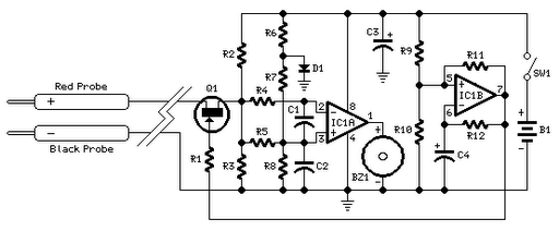
Measurements were conducted using a modified program to measure the voltage applied at the drive electrode and the voltage at the sense electrode. Conductance was calculated using the formula 0.01S * V_resist / (V_applied * V_resist). The initial version...
LEDs lining the headliner will fade in when the door is opened and fade out when the door is closed. The necessary components include a circuit to utilize 12V power from the vehicle to illuminate 15 LEDs and control...
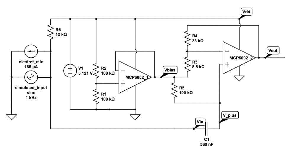
This circuit generates a two-tone effect similar to the cuckoo song. It can be utilized for doorbells or other applications due to its integrated audio amplifier and loudspeaker. When used as a sound effect generator, it can be connected...