
fade fade out led circuit car interior lighting
The proposed circuit for controlling the LED headliner lighting involves a combination of analog and digital components to achieve the desired fading effect. The core of the system is the 555 timer configured in astable mode, which generates a PWM signal. This signal is then fed to a MOSFET, which acts as a switch to control the power delivered to the LED array. The choice of a MOSFET is advantageous due to its high efficiency and low on-resistance, minimizing heat generation during operation.
The RC charge pump circuit is essential for managing the brightness of the LEDs. A capacitor is charged when the door is opened, allowing the voltage across it to rise. The duty cycle of the PWM signal from the 555 timer determines how much of this voltage is applied to the LEDs, thus controlling their brightness. A potentiometer can be included in the circuit to allow for manual adjustment of the brightness level.
For the fading-out effect, the 555 timer can be configured in monostable mode. Upon closing the door, the timer starts a predetermined delay (e.g., 5 seconds) before transitioning the output to low, allowing the capacitor to discharge through the LEDs. This gradual discharge creates a smooth dimming effect, enhancing the user experience.
In addition, the integration of a voltage-to-PWM converter can provide a more sophisticated control mechanism. This converter can take the voltage across the capacitor and convert it into a PWM signal, allowing for more precise control over the LED brightness without the need for complex programming.
To ensure the system operates reliably without draining the vehicle's battery, careful consideration must be given to the quiescent current. Employing an RC circuit on the gate of the MOSFET can help mitigate this issue by ensuring that the MOSFET remains off when the vehicle is not in use.
Overall, this circuit design not only meets the functional requirements of fading LED illumination but also serves as a practical introduction to electronic circuit design and programming for future projects.LED`s lining the headliner, and have them fade in when the door is opened, fade out when the door is closed. I think it should be simple. from what i gather i`m going to need: i don`t really know. basically i need to know what circuits will be necessary to use 12v power from the vehicle to illuminate 15 leds, and fade them in/out when the doors are opened/closed He can use the 555 as a PWM driver into a Power
MOSFET into a Capacitor with the load acting as the R component in the RC Charge pump. Thus the duty cycle of the 555 governs the voltage seen by the load and controls the brightness via a potentiometer. the fade out seemed to me like it could be done with a 555 monostable using a capacitor between the output and the LEDs, thus the door closes, a 5 second delay, then the 555 output goes low, and the cap discharges to dim the lights But to entertain the other thoughts, you may not need linear dimming.
e. g. The voltage across a capacitor might be able to contol a voltage to PWM converter. Velleman makes a voltage to PWM circuit board. So, I`m thinking. When the door opens apply full voltage to the PWM thingy. (Actually it has a slow start feature) and apply a buffered output of the voltage across the capacitor from a RC circuit. You probably will have to power the RC circuit from the always on circuit. What I`m thinking of is somthing that could charge a cap when the door is open and remove the charging source and connect a resistor in parallel when the door closes.
Use the buffered voltage acroos the cap to drive the PWM thingy. I think quiesent currents will get in the way. e. g. the current drain on the battery when the car is off. Maybe just a simple RC on the gate of a mosfet will do the trick. The mosfet will dissipate a bit of heat during the ramp up/down, so if it gets hotter than you`d like, put in on a heatsink (insulated from the car body). Overwise you need to learn it by yourself plus buy (or make) some basic programmer hardware, this may be not what you are looking for, if it is just a one-time project.
If you want to learn something in this direction this project is a good way to start though. zman, thank you so much. It is a one time project, but i`m finding myself thinking of more and more projects that will require programming. Time to learn it. 🔗 External reference
Related Circuits
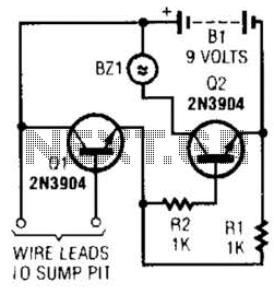
A common collector amplifier drives a 2N3904 switch to sound alarm BZ1. The wire leads to a water sensor or sump pit, level switch, etc. It is used to allow the alarm to operate and be mounted in a...
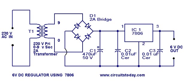
A simple 6-volt DC regulator circuit with a diagram and schematic using the 7806 IC, a positive voltage regulator. It serves as an elementary 6-volt, 1-ampere power supply circuit. The 7806 voltage regulator is a widely used integrated circuit that...
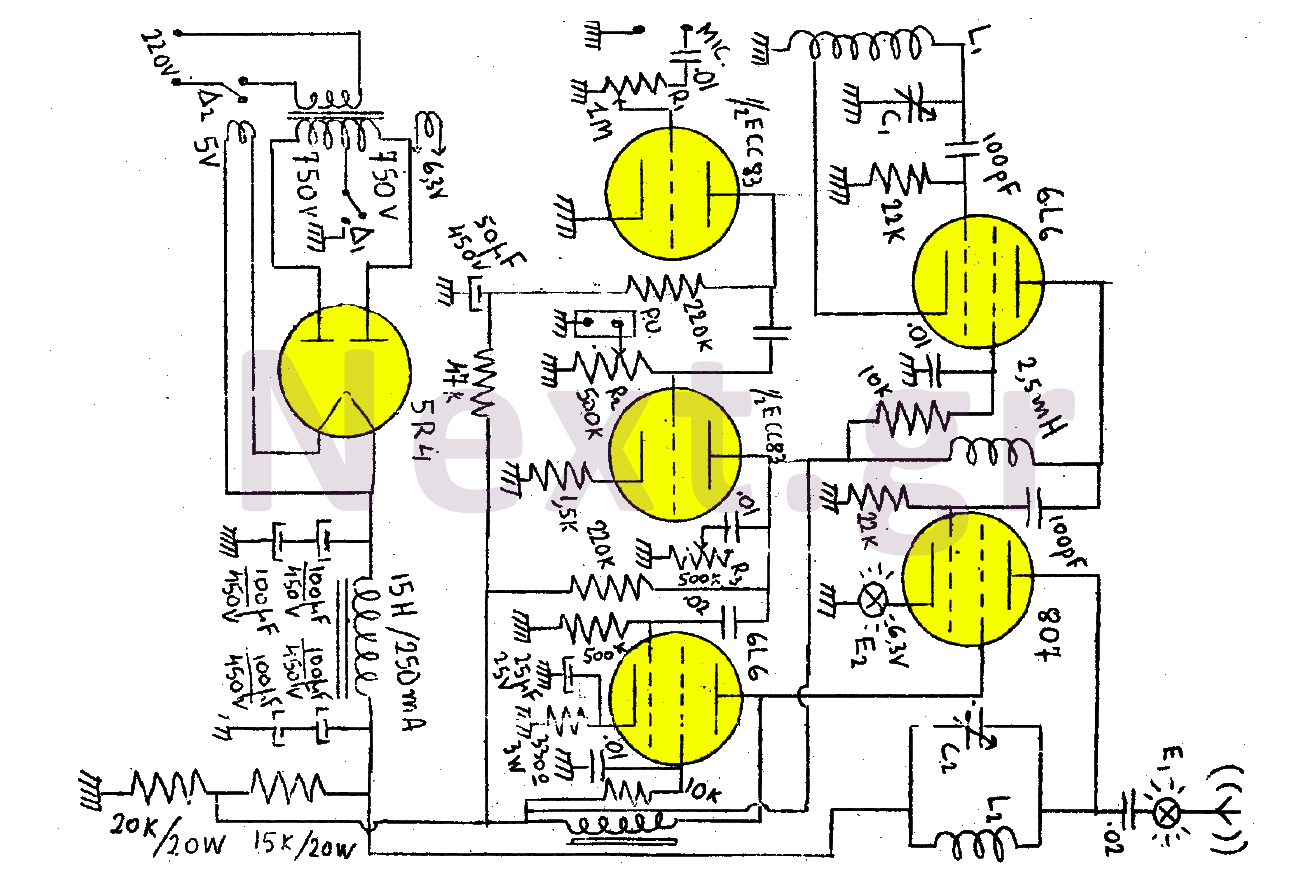
This transmitter consists of a total of five bulbs. The 6L6 tube functions as an oscillator, directing oscillations to the grid of the 807 tube, which serves as the final amplifier and the transmitter output lamp. The amplifier includes...
Pinout of a smart card (SIM card) to PC adapter cable (SIM reader/writer) schematic and layout of a 6-pin SIM card special connector and a 9-pin D-SUB female connector used to connect computers to ISO 7816 compatible chip card...
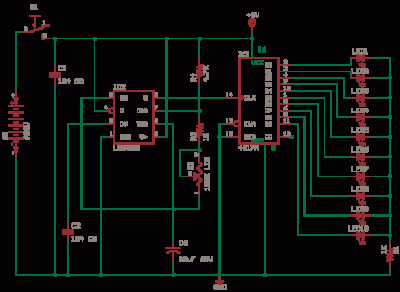
The 555 Astable generates a clock for this circuit, functioning as an oscillator that produces a square wave output at pin 3. This output is counted by the CD4017 decade counter, which creates a running lights effect. The CD4017...
The first half of the circuit (IC1a) features an input sensitivity of 3 mV and includes a frequency correction network consisting of capacitors C5, C3, and resistors R6 and R8. The bass signal from the phono input is amplified,...
Warning: include(partials/cookie-banner.php): Failed to open stream: Permission denied in /var/www/html/nextgr/view-circuit.php on line 713
Warning: include(): Failed opening 'partials/cookie-banner.php' for inclusion (include_path='.:/usr/share/php') in /var/www/html/nextgr/view-circuit.php on line 713