
Noise making circuits

The described circuit operates as a versatile audio signaling device, suitable for various applications where sound alerts are required. The two-transistor flasher mechanism allows for dynamic frequency modulation, resulting in a customizable audio output. The interaction between the capacitors and resistors plays a crucial role in defining the sound's characteristics, including pitch, volume, and decay time. The choice of transistors also impacts performance; therefore, selecting appropriate small-signal transistors ensures reliability and efficiency. The circuit's design allows for easy adjustments, making it adaptable to different sound requirements. The use of a Darlington pair for buffering enhances the output drive capability, ensuring that the speaker receives sufficient power to produce audible tones. The overall design emphasizes low power consumption during idle states, which is particularly advantageous for battery-operated devices. By modifying component values, users can experiment with various sound profiles, making this circuit a valuable tool for creating sound alerts in automotive applications, alarms, or novelty devices.The heart of the circuit is the two transistor flasher with frequency modulation applied to the base of the first transistor. When the pushbutton is depressed, the frequency of oscillation climbs to a peak and when the button is released, the frequency descends due to the rising and falling voltage on the 22 uF capacitor.
The rate of change is det ermined by the capacitor value and the 100k resistor from the pushbutton. The oscillation eventually stops if the button is not depressed and the current consumption drops to a tiny level so no power switch is needed. The 0. 1 uF determines the pitch of the siren: A 0. 047uF will give a higher pitch siren and a 0. 001 uF will give an ultrasonic (at least for me, anyway) siren from 15 to 30 kHz which might have an interesting effect on the neighborhood dogs!
The 33k resistor from the collector of the PNP to the base of the NPN widens the pulse to the speaker giving greater volume. The flasher circuit drives a PNP transistor which powers the speaker. This transistor may be a small-signal transistor like the 2N4403 in most applications since it will not dissipate much power thanks to the rapid on-and-off switching.
The 100 ohm and 100uF capacitor in series with the speaker limit the current to about 60 mA and they may be replaced with a short circuit for a louder siren as long as the transistor can take the increased current. The prototype drew about 120 mA when shorted which is fine for the 2N4403. Transistor substitutions should be fine - try just about any small-signal transistors but avoid high frequency types so that you do not end up with unwanted RF oscillations.
This circuit simulates a chime similar to the sound many cars make when the keys are left in the ignition. The bottom two gates form a squarewave audio oscillator that drives the base of the 2N4401, turning it on and off at an audio rate.
The top two gates produce a short low-going pulse about once per second that discharges the 10 uF capacitor through the diode. The voltage then jumps up and slowly decays through the 15 k collector resistor when the 2N4401 is conducting.
The result is a squarewave on the collector of the 2N4401 that jumps up quickly then decays slowly. The darlington emitter-follower buffers the squarewave and drives a small speaker. The tone frequency is set by the 1000 pF capacitor and the cadence of the chime is set by the 0. 1 uF capacitor. The 10 uF capacitor determines how quickly the chime dies out and the 3. 3 k/3. 3 uF soften the attack time of the leading edge of the chime. The volume is set by the 22 ohm resistor and 100 uF bypass capacitor. These values may be experimentally varied to produce the desired sound. 🔗 External reference
Related Circuits
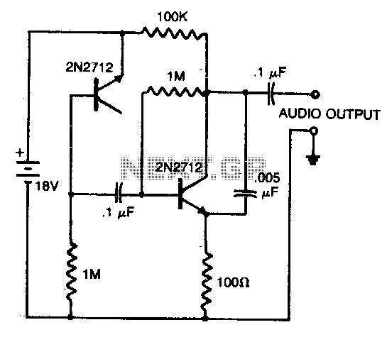
A reverse-biased pn junction of a 2N2712 transistor is utilized as a noise generator. The second 2N2712 functions as an audio amplifier. A 0.005 µF capacitor placed across the amplifier output eliminates certain high-frequency components, allowing for a closer...
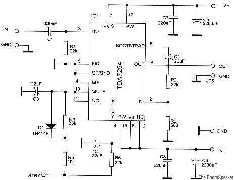
The TDA7294 is a monolithic integrated circuit housed in a Multiwatt15 package, designed to deliver high output power of up to 100W. It is intended for use as an audio Class AB amplifier in high-fidelity applications. The TDA7294 is a...
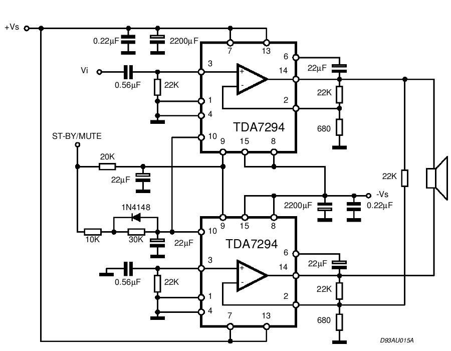
The TDA integrated circuit series is highly regarded and widely utilized in amplifier designs and projects. TDA audio amplifier circuits are primarily produced by Philips and SGS-THOMSON. The most commonly used ICs include the TDA2030 and TDA2003 for small...
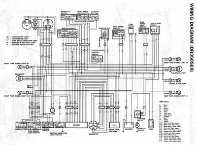
The following circuit illustrates the electrical circuit diagrams for the Toyota Supra. The diagrams indicate the point at which the power source is received. The electrical circuit diagrams for the Toyota Supra provide a comprehensive overview of the vehicle's electrical...
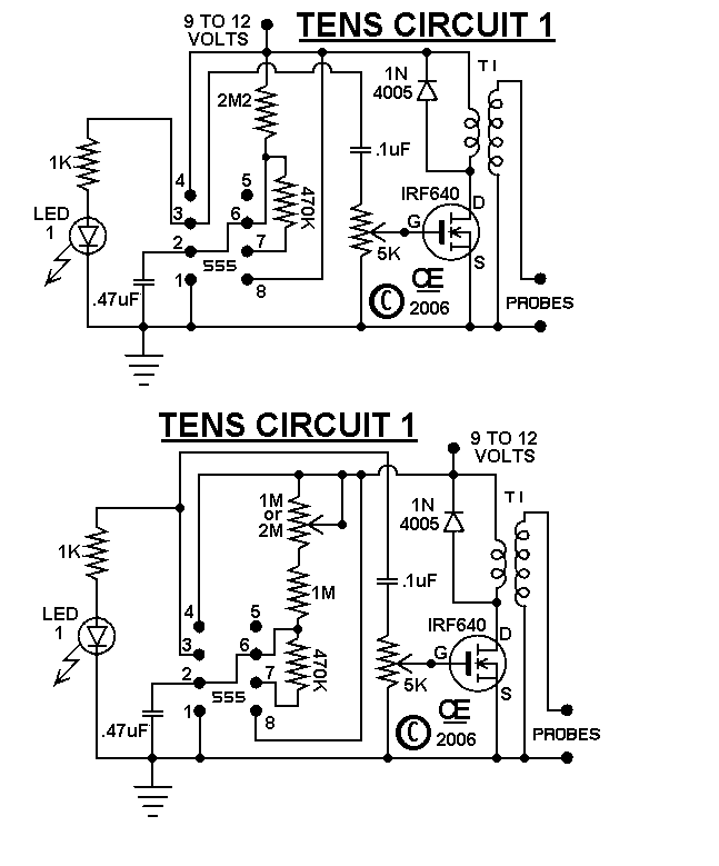
The circuits were originally designed for an individual with muscle issues. Although they were reported to function effectively, the use of these devices is not recommended for anyone, and no responsibility or liability is accepted for their assembly or...
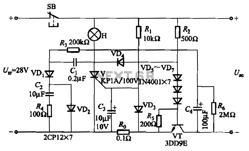
Capacitor C3 is used to determine the cutoff power, specifically the voltage threshold (VT cutoff), which influences the delay time selection. The schematic includes a reset button, SB, that is utilized to reset the system after a failure has...