
TENS Circuits
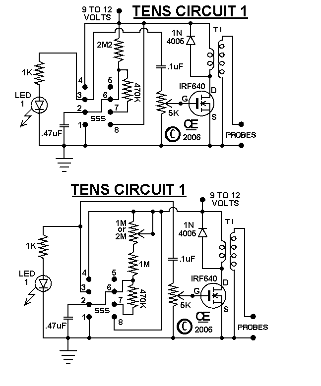
The described circuit includes several critical components that contribute to its operation. The audio transformer (T1) plays a vital role in signal coupling, allowing for impedance matching between the circuit and the load. The 8-ohm impedance is suitable for driving speakers or other low-impedance loads. The Field Effect Transistor (FET) serves as a switch or amplifier, with the Base, Collector, and Emitter connections indicating that a bipolar junction transistor (BJT) configuration is being referenced, which is essential for controlling the output signal.
The recommended Mode Transformer (Part Number 60-282-0) is specifically designed to optimize performance in this application. The connection of the Base to the Gate, Collector to the Drain, and Emitter to the Source suggests that the circuit may be intended for use in a switching application where the FET is being driven by a BJT.
The inclusion of a potentiometer for frequency control of the 555 timer allows for flexibility in tuning the circuit's operational frequency. The 555 timer is widely used for generating precise timing pulses and can be configured in various modes, such as astable or monostable. The option to short the potentiometer provides a straightforward method for users who prefer a fixed frequency operation.
For those opting to implement the frequency control, selecting a potentiometer with a resistance value of 1M or 2M will affect the timing characteristics of the 555 timer. Additionally, changing the resistor R1 from 2M2 to 1M will further modify the timing cycle, allowing for a broader range of frequency adjustments. This design consideration is crucial for applications requiring precise timing and control.
Overall, the circuit design emphasizes a balance between functionality and user control, with specific recommendations for component values and configurations to ensure optimal performance.I initially designed these circuits for a friend who had muscle problems and while he says they did work well for him, I "DO NOT" RECOMMEND THE USE OF THESE DEVICES BY ANYONE FOR ANY REASON. I ACCEPT NO RESPONSIBILITY OR LIABILITY FROM THERE ASSEMBLY OR USE IN ANYWAY. "T1" in Circuits "1 & 2" is a small audio transformer with the 8 ohm impedance w inding connected to the Fet and the larger winding connected to the probe and ground. I Recommend using a "Mode" Transformer, Part Number 60-282-0. The Base connects to the Gate, the Collector to the Drain, and the Emitter to the Source. This change will result in a "Lower Power Output", but it still works. The PCB for the Ten-1 also has provisions for a pot to control the Frequency of the 555. If you don`t want to use this control, Just Short it out. If you do want this control, use a 1M or 2M Pot and Change R1 (2M2) to a 1M. 🔗 External reference
Related Circuits
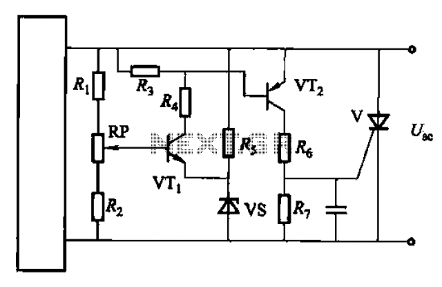
Both circuits are designed solely for overcurrent protection in power supply applications. The circuits in question serve as critical components in safeguarding power supply systems from overcurrent conditions. Overcurrent protection is essential in preventing damage to electrical components and...
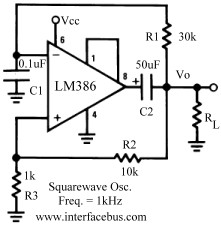
Several operational amplifier circuits are presented here, configured as square wave oscillators. A square wave is a periodic pulse train with a 50 percent duty cycle. The operational amplifier functions as a high-gain amplifier, and oscillation is achieved with...
A simple test circuit designed for troubleshooting audio and radio equipment. It can inject a square wave signal rich in harmonics or be used with headphones as an audio tracer. A single-pole double-throw switch is utilized to toggle between...
NOTE: There is no guarantee as to the suitability of said circuits and information for any purpose whatsoever other than as a self-training aid. I.E. If it blows your equipments, trashes your hard disc, wipes your backup, burns your...
Over 1400 top electronics projects and electronic circuits with photos, datasheets, and easy-to-read schematics, along with explanations of how they work and how to build them. The collection comprises a vast array of electronics projects suitable for enthusiasts and professionals...

A field strength meter utilizing a biased Schottky detector employs a temperature-compensated Schottky diode within an amplified, untuned field strength indicator powered by two AA cells. This device indicates the relative field strength of RF fields ranging from a...