Non-Contact Power Monitor
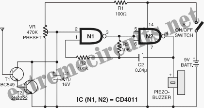
This is a simple non-contact AC power monitor designed for home appliances and laboratory equipment that should remain continuously powered. A failure of the fuse or a power outage in the equipment can lead to significant damage if unnoticed. The monitor activates an alarm when it detects a power failure. The circuit utilizes CMOS IC CD4011 and consists of only a few components. The NAND gates N1 and N2 of the IC are configured as an oscillator that directly drives a piezo buzzer. Resistors R2 and R3, along with capacitor C2, form the oscillator components. An amplifier made up of transistors T1 and T2 disables the oscillator when mains power is present. In standby mode, T1 picks up the 50Hz mains hum during the positive half cycles of AC, allowing it to conduct. This, in turn, provides base current to T2, which also conducts, pulling the collector to ground potential. As the collectors of T1 and T2 are connected to pin 2 of NAND gate N1 of the oscillator, the oscillator is disabled when the transistors are conducting. Capacitor C1 prevents the collector voltage of T2 from rising again during the negative half cycles. When power fails, the electrical field around the equipment's wiring ceases, causing T1 and T2 to turn off. Capacitor C1 begins charging through R1 and preset VR, and once sufficiently charged, the oscillator is enabled, causing the piezo buzzer to emit a loud tone. Resistor R1 protects T2 from a short circuit if VR is set to zero resistance. The circuit can be easily assembled on a perforated board or breadboard. A small plastic case can be used to enclose the circuit, with a telescopic antenna serving as the aerial. A 9V battery powers the circuit, which consumes only a few microamperes in standby mode, allowing the battery to last for several months. After assembly, the aerial should be placed near the mains cable, and VR should be adjusted until the alarm stops, indicating standby mode. The circuit can be positioned on the equipment being monitored, close to the mains cable.
The non-contact AC power monitor is engineered to continuously monitor the power supply to critical equipment, ensuring that any power interruptions are promptly detected. The design is based on a straightforward oscillator configuration utilizing NAND gates from the CD4011 CMOS IC, which is known for its low power consumption and high reliability. The oscillator generates an audible signal through a piezo buzzer, alerting users to power failures.
The circuit's operation hinges on the behavior of transistors T1 and T2, which act as an amplifier and switch. When the device is powered, T1 detects the 50Hz frequency of the AC mains, allowing it to remain in a conductive state. This conduction keeps T2 activated, effectively disabling the oscillator and preventing the buzzer from sounding. Capacitor C1 plays a crucial role in maintaining the stability of the circuit by preventing unintended oscillations during the AC cycle's negative phase.
In the event of a power failure, the absence of the mains hum results in T1 and T2 turning off, which allows capacitor C1 to charge through R1 and VR. Once the voltage across C1 reaches a threshold level, it triggers the oscillator, leading to the activation of the piezo buzzer. This feature is essential for alerting users to potential issues that could lead to equipment damage.
The component selection is optimized for simplicity and cost-effectiveness, making the circuit suitable for DIY projects or for use in environments where continuous monitoring is necessary. The use of a 9V battery ensures portability and ease of use, while the low standby current draw enhances battery life. The assembly is straightforward, allowing for quick prototyping on a breadboard or perforated board, and the compact design facilitates easy integration into various applications.
Overall, this circuit serves as an effective solution for monitoring AC power continuity in critical applications, providing both a practical alert system and a reliable means of safeguarding valuable equipment against power-related failures.Here is a simple non-contact AC power monitor for home appliances and laboratory equipment that should remain continuously switched-on. A fuse failure or power breakdown in the equipment going unnoticed may cause irreparable loss. The monitor sounds an alarm on detecting power failure to the equipment. The circuit is built around CMOS IC CD4011 ut ilising only a few components. NAND gates N1 and N2 of the IC are wired as an oscillator that drives a piezobuzzer directly. Resistors R2 and R3 and capacitor C2 are the oscillator components. The amplifier comprising transistors T1 and T2 disables the oscillator when mains power is available. In the standby mode, the base of T1 picks up 50Hz mains hum during the positive half cycles of AC and T1 conducts.
This provides base current to T2 and it also conducts, pulling the collector to ground potential. As the collectors of T1 and T2 are connected to pin 2 of NAND gate N1 of the oscillator, the oscillator gets disabled when the transistors conduct. Capacitor C1 prevents rise of the collector voltage of T2 again during the negative half cycles. When the power fails, the electrical field around the equipment`s wiring ceases and T1 and T2 turn off.
Capacitor C1 starts charging via R1 and preset VR and when it gets sufficiently charged, the oscillator is enabled and the piezobuzzer produces a shrill tone. Resistor R1 protects T2 from short circuit if VR is adjusted to zero resistance. The circuit can be easily assembled on a perforated/breadboard. Use a small plastic case to enclose the circuit and a telescopic antenna as aerial. A 9V battery can be used to power the circuit. Since the circuit draws only a few microamperes current in the standby mode, the battery will last several months.
After assembling the circuit, take the aerial near the mains cable and adjust VR until the alarm stops to indicate the standby mode. The circuit can be placed on the equipment to be monitored close to the mains cable. 🔗 External reference
