
Power failure detector
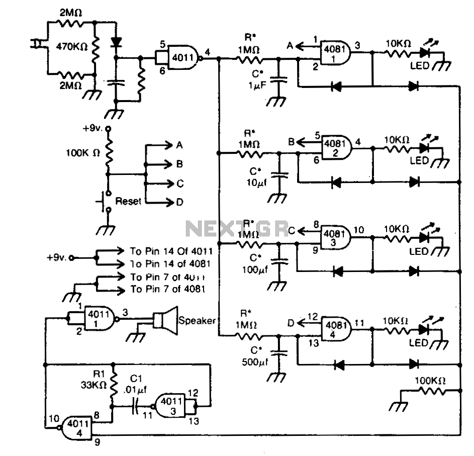
The described circuit functions as a power outage indicator, utilizing a timing mechanism to signal the duration of an outage. The timing is determined by the resistor (R*) and capacitor (C*) values, which create a time constant that governs how long the circuit remains active after power is restored. The circuit is designed to provide visual or audible feedback corresponding to the specific duration of the outage, allowing users to understand the length of the interruption.
When a power failure occurs, the capacitor begins to discharge through the resistor, and the voltage across the capacitor will decrease over time. The circuit may include a microcontroller or a simple comparator that monitors the voltage level. Depending on the threshold set within the circuit, different output signals can be activated for each specified duration of the outage—1 second, 10 seconds, 100 seconds, and 500 seconds.
The Reset button serves as a manual control to clear the circuit’s state and prepare it for future power outages. When pressed, it reinitializes the system, allowing it to start monitoring for power interruptions again. This feature ensures that the circuit does not retain the previous state after a reset, thus providing accurate and reliable performance.
Additional components may include LEDs for visual indication or a buzzer for an audible alert, depending on the design requirements. The schematic would typically include a power supply section, the timing circuit composed of R* and C*, the reset mechanism, and the output indicators. Proper selection of R* and C* values is crucial for achieving the desired timing intervals and ensuring the circuit operates within the specified parameters.This circuit indicates that a power outage occured for 1, 10, 100, and 500 seconds with the values given for R* and C* After a power failure, the circuit can be reset by pushing the Reset button. 🔗 External reference
Related Circuits
Sometimes amateurs like to home-brew their power supplies instead of purchasing one off the shelf at any of the major ham radio retail dealers. The advantage to rolling your own power supply is that it teaches us how they...
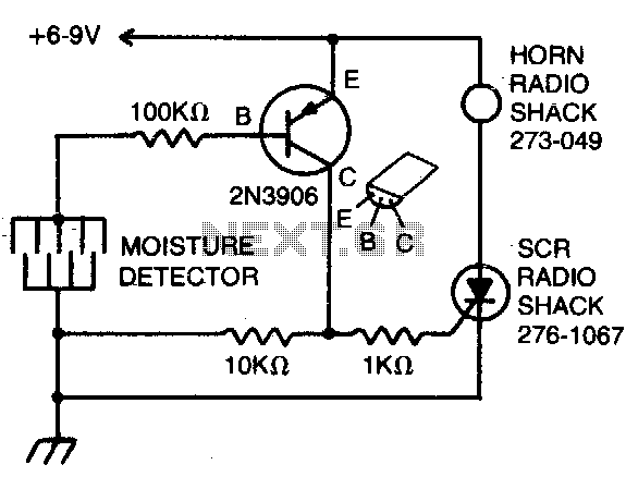
The detector consists of fine wires spaced approximately one to two inches apart. When the area between a pair of wires becomes moist, an alarm will sound. To deactivate the alarm, the DC power must be disconnected. The described moisture...
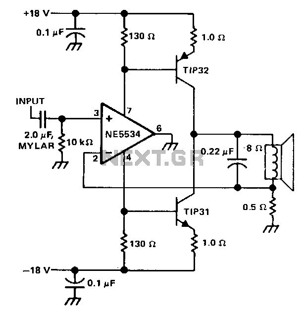
The single speaker amplifier circuit utilizes current feedback instead of the more commonly used voltage feedback. The feedback loop originates from the junction of the speaker terminal and a 0.5-ohm resistor, connecting to the inverting input of the NE5534...
The circuit is divided into two sections: the isolated external loop connected to the remote interface connector on the front of the power supply unit (PSU) and the non-isolated inner loop connected to the high-tension (AC line) supply. The...
Power diagram videos for a DIY solar panel system wiring diagram. This is an exact diagram of the power window wiring diagram available in printed books on Amazon, covering power door locks and wiring diagrams. The provided description outlines a...
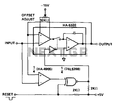
An analog signal requires approximately 100 ns to propagate through the HA-5320. For time-varying signals, this ensures a voltage difference between input and output. Additionally, the voltage changes polarity when the signal slope changes polarity (crosses a peak). This...
Warning: include(partials/cookie-banner.php): Failed to open stream: Permission denied in /var/www/html/nextgr/view-circuit.php on line 713
Warning: include(): Failed opening 'partials/cookie-banner.php' for inclusion (include_path='.:/usr/share/php') in /var/www/html/nextgr/view-circuit.php on line 713