
Nostalgic Crystal Radios
The circuit design described is a simple yet effective AM radio receiver that operates without traditional power sources. The core components include a crystal diode, an inductor, a capacitor, and a high-impedance headphone or an operational amplifier with low-impedance headphones. The antenna, a critical element, is a 10-meter long wire that captures radio frequency signals. Proper insulation from the ground is essential to reduce signal loss due to stray capacitance, which can degrade the quality of the reception.
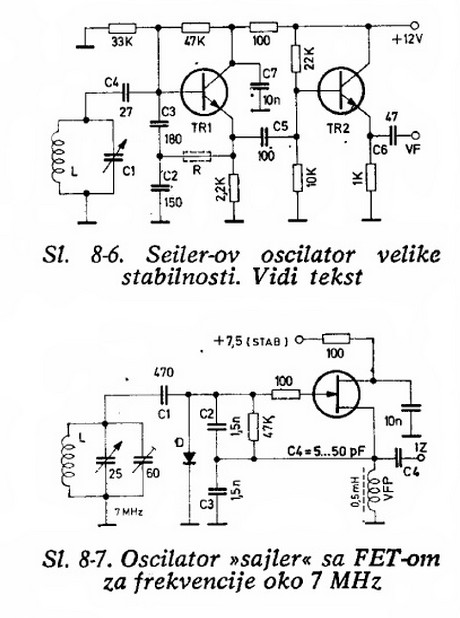
The resonant circuit formed by the inductor and capacitor is tuned to the desired radio station frequency. The frequency is determined by the formula F = 1 / (2 * π * √(L * C)), where L is the inductance and C is the capacitance. By adjusting the variable capacitor (C1), the circuit can be tuned to different stations, allowing for the selection of various AM signals.
The rectification process is performed by the diode, which converts the received alternating current (AC) signal into a direct current (DC) signal. This signal is then smoothed by the capacitor (C2), which filters out any remaining AC components, providing a stable audio output. High-impedance headphones are preferred due to their sensitivity; they can produce audible sound even with minimal current flow. In scenarios where high-impedance headphones are unavailable, an operational amplifier can be integrated into the circuit to amplify the audio signal sufficiently for standard low-impedance headphones.
The construction of this circuit emphasizes the use of readily available materials, showcasing the ingenuity required to create functional electronics from limited resources. This design not only serves as a practical radio receiver but also as a testament to the resourcefulness of individuals in challenging situations, such as prisoners in camps or soldiers in the field.Apart from the diode (which replacement would need a PbS, Lead Sulphyde, galena cristal) everything you can see in the circuit (for the no power version) can be built with enamel wire, alluminium cooking foil, carton wax and so on. The real painful part is to find a high impedance headphone, it is unlikely yo find one at present day but it is possible.
In addition I substituted an high internal impedance headphone with a opamp and normal The AM signal is captured by the antenna, 10 mt long horizontal wire, WELL insulated from earth (I mean distant, to lower the stray capacitance coupling with ground which will adsorb some signal ). The Inductor and capacitor forms a resonator, that will tune with the station which frequency is F= 1/ (2*pi*sqrt(L*C), so adjust C1 for tuning.
The signal is rectified (demodulated) and smoothed by C2. The high impedance headphones has fine internal wiring and lots of windings, so even a small current will produce an audio output. 10 mt of electrical wire, WELL insulated from ground (use plastic bottle caps and hoowup wire to keep it high).
This must be the arrangement |=wall. =hookup wire o=plastic cap -=wire antenna : Amplifier + low impedance headphones: Use a general purpose opamp with feedback resistors and a low impedance headphone (as these of cassette, cd players), but you need power. :-( It is very nice to build, hearing a sound of a radio station without power is very fun. I reconstrected it basing on my fathers rememberings and very old texts, improved a bit with some physics.
Constructing from almost anything is possible, even the headphone, as many cristal radios have been found in nazis prison camps build by prisoners from very limited resources (as everything in a prison camp) and some in foxholes (called foxhole radios). 🔗 External reference
Related Circuits
Will an LC-based oscillator be able to demonstrate performance comparable to crystals under such conditions (possibly in unusual configurations like LC-opamp) so that any energy loss at each stage is recovered, resulting in a narrower bandwidth? Examine some amateur...
The FV-1 features internal circuitry that supports an external crystal, ideally a 32.768 kHz watch crystal. These crystals are very affordable and readily available. While other frequencies are available, they are not as cost-effective or common. If the system...
The LA2010 is an integrated circuit designed for detecting interprogram spaces, allowing for the identification of the starting point of a program that immediately precedes or follows a musical program recorded on tape. It is manufactured by Sanyo Semiconductor...
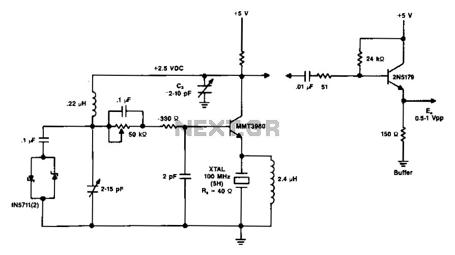
The diagram illustrates a 100 MHz oscillator functioning on the fifth harmonic. To preserve the transistor's gain, it is important to note the increase in the collector's load resistance, Rl, due to the rise in the quartz crystal's internal...
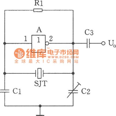
The image depicts a sine wave oscillator that consists of a quartz crystal (SJT) and gate A of the hex inverter IC CD4069. Compared to a standard RC phase-shift oscillator, the frequency stability of a crystal oscillator can achieve...
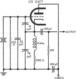
The fundamentals of crystals have not changed since this article appeared in a 1960 edition of Popular Electronics. The methods for growing, cutting, and packaging crystals have evolved significantly. Understanding their operation at the atomic level has also advanced...