
Notebook computer chip power supply circuit
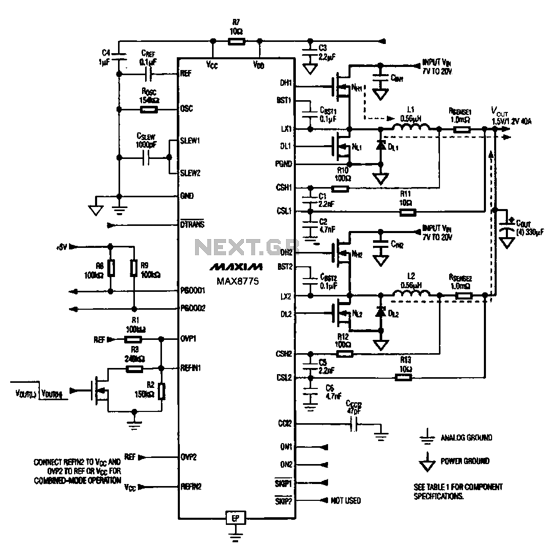
The notebook computer chip power supply circuit utilizes the MAX8775 integrated circuit to generate a Pulse Width Modulation (PWM) signal. The MAX8775 is a high-efficiency step-down voltage regulator designed to provide a stable output voltage for various components in notebook computers.
The circuit typically includes several key components: the MAX8775 itself, input capacitors to filter the power supply, output capacitors to stabilize the output voltage, and inductors to smooth the current flow. The PWM signal generated by the MAX8775 controls the switching of the output transistor, which regulates the voltage supplied to the notebook chip.
In operation, the MAX8775 monitors the output voltage and adjusts the duty cycle of the PWM signal to maintain the desired voltage level. This feedback mechanism ensures that the output remains stable despite variations in load current or input voltage. The design may also include additional features such as over-voltage protection, thermal shutdown, and soft-start functionality to enhance reliability and performance.
Overall, the notebook chip power supply circuit employing the MAX8775 is critical for delivering the necessary power with high efficiency and minimal noise, contributing to the overall performance and longevity of the notebook computer.Notebook computer chip power supply circuit Notebook chip power supply circuit which generates the PWM circuit using MAX8775.
Related Circuits
This schematic has been modified from an old Bell & Howell projector amplifier for model 302, utilizing PP 6V6 tubes with a 12AU7 phase inverter (PI). The PI circuit appears to be closest to a "floating paraphase." There is...
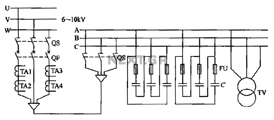
The compensation system is designed to focus on a high-pressure, high-voltage capacitor bank installed in the substation 6-10 kV bus. Compensation can only be implemented in this manner for the 6-10 kV bus before the reactive power on the...
A new member has joined the forum and is seeking assistance with electronics, particularly from a technical engineering perspective, although they have some experience with circuits and schematics. The individual is likely looking to enhance their understanding of electronic components,...
The following circuit illustrates a 5 Zone Anti-Theft Circuit Diagram. This circuit is based on the CMOS 4050B IC. Features: the system may comprise in... The 5 Zone Anti-Theft Circuit utilizes the CMOS 4050B integrated circuit, which is a hex...

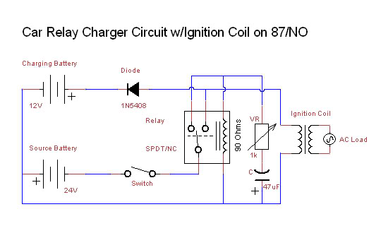
If the total circuit resistance can be significantly reduced to less than 0.1 Ohm and a load of 0.4 Ohm or less is connected, over 1 kilowatt of free electrical energy can be obtained. There are two discrete voltage...
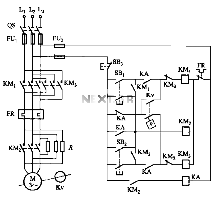
The circuit shown in Figure 3-129 is the C650-2 lathe brake control circuit, utilizing a speed control relay. The C650-2 lathe brake control circuit is designed to manage the braking mechanism of a lathe machine effectively. This circuit incorporates a...