
High-pressure centralized compensation capacitor circuit
The described compensation system employs a high-voltage capacitor bank to enhance the power factor of a substation operating at 6-10 kV. This system is particularly relevant in industrial applications where reactive power management is crucial for efficient operation. The capacitor bank serves to counteract the inductive effects of loads, thereby improving the overall power factor and reducing energy costs associated with reactive power penalties.
The capacitor bank is strategically connected to the substation's bus, allowing for centralized control and monitoring. Each capacitor unit within the bank is equipped with high-voltage fuses to safeguard against overcurrent conditions that could lead to failures or safety hazards. The use of packaged capacitor cabinets not only simplifies the installation process but also enhances safety by containing potential failures within a controlled environment.
The discharge mechanism is critical in ensuring safety when the capacitor bank is de-energized. The auxiliary voltage transformer provides a reliable means of discharging stored energy, mitigating risks associated with residual voltage. Compliance with GB50053-1994 ensures that the installation meets national safety standards, thus providing a framework for the safe operation of high-voltage capacitor systems.
In summary, this compensation system is designed to effectively manage reactive power in high-voltage substations, ensuring compliance with safety standards while optimizing the power factor of the electrical system. This design approach is particularly beneficial in large industrial settings where energy efficiency and operational reliability are paramount. Compensation is to focus on high-pressure high-voltage capacitor bank focused on the plant installed in the substation 6-10kV bus. Compensation can only be compensated in this way 6-lOkV bus before the reactive power on the line, and reactive power plant after the bus line are not abundant h compensation, so this way compensation was better than the last two economic compensation way difference. But less initial investment in this way compensate for centralized operation and maintenance, but also the high-pressure side of the plant reactive power effective reactive power compensation, in order to meet the requirements of the plant total power factor, so in this way to compensate in some large medium plant applications quite common.
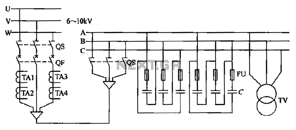
FIG shunt capacitor banks is centralized wiring diagram compensation connected substation 6 ~ lOkV bus. Here coupling capacitor bank uses, housed in the package capacitor cabinet. In order to prevent short circuit capacitor breakdown caused by phase, so each side shaped junctions are connected with high-voltage fuse protection.
Since the residual voltage of the capacitor removed from power Ah, the residual voltage of up to peak power grid voltage, which is the root of personal danger, it must be installed discharge device. Figure TV auxiliary voltage transformer primary winding is used to discharge. To ensure reliable discharge the capacitor bank shall not be installed in the discharge circuit fuse or switch.
Press GB50053-1994 regulations. Indoor high voltage capacitor means should be provided in a separate room, when a small group capacity capacitor can be set in the high-pressure distribution room, but the distance from the high voltage electrical installations should not be less than 1. 5m.
Related Circuits
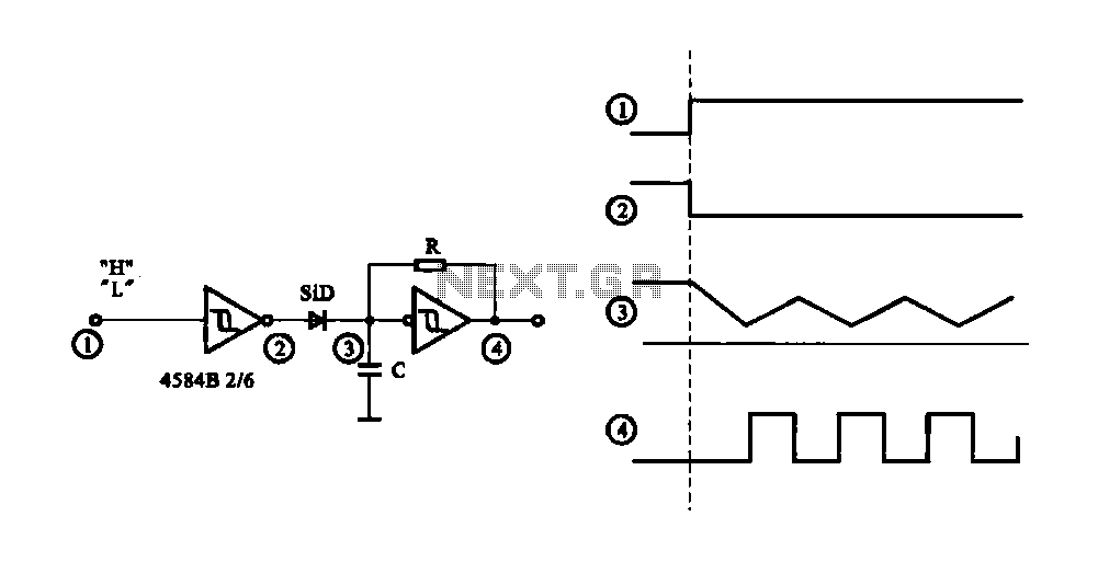
The circuit generates a controlled pulse signal. When a high pulse signal is applied to the input terminal O (start), the output pulse signal is activated. Conversely, when a low signal is received at the input terminal O (stop),...
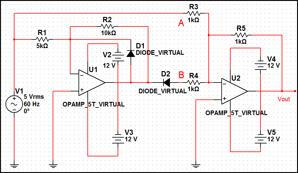
The optimal operational amplifier circuit used to convert a sine waveform into a rectangular waveform is the Schmitt trigger circuit. The Schmitt trigger circuit is a vital component in signal processing, particularly for converting analog signals into digital signals. It...
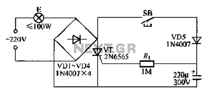
This circuit is a simple connection delay lamp circuit. When the lights are turned on and the switch is pressed, the power supply is activated. The capacitor charges rapidly, causing the thyristor (VT) to open, which in turn lights...
This digital DIY tachometer for bicycles utilizes two reed switches to gather speed information. The reed switches are positioned near the wheel rim, where permanent magnets, attached to the wheel spokes, pass by and activate the switches. The speed...
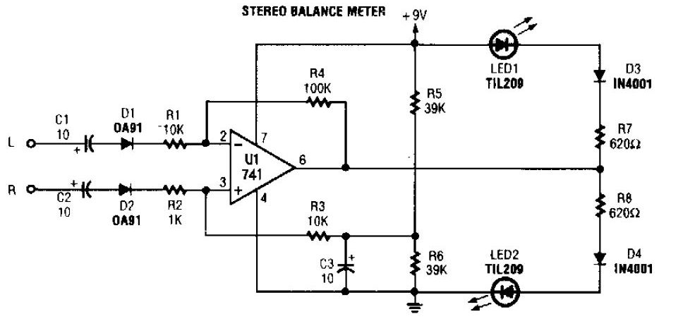
The simplest stereo balance meter circuit schematic available on the internet. When the left and right signals are equal, no output is present from U1 and pin. This stereo balance meter circuit is designed to visually indicate the balance between...
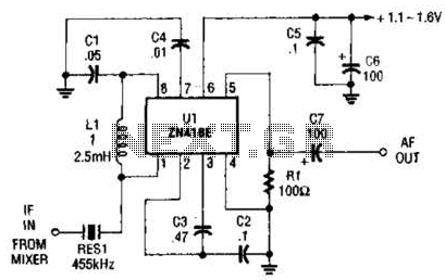
Up to 60 dB of gain at 455 kHz is available with the MC1350P. RES1 is a ceramic resonator, LC, or crystal filter. Keep the leads to pins 1, 2, 3, and 7 short. The MC1350P is a versatile integrated...