
Ntsc/Rgb Video Decoder
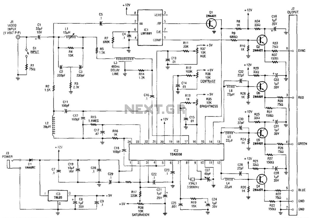
The NTSC/RGB decoder circuit employs the TDA3330 integrated circuit, which is specifically designed for decoding NTSC video signals. The TDA3330 processes a 1-V peak-to-peak input video signal, effectively separating it into its individual color components: red, green, and blue. This separation is critical for applications involving RGB monitors, which require distinct color signals for accurate display.
The integrated sync separator, represented by U1 (LM1881), plays a vital role in this circuit by extracting the synchronization signals from the composite video input. The LM1881 is capable of detecting the sync pulses embedded within the video signal and providing a clean, separated sync output. This output is essential for ensuring that the RGB monitor can synchronize its display with the incoming video signal, thus preventing issues such as image tearing or misalignment.
To implement this circuit, the TDA3330 requires appropriate power supply connections and input/output configurations. The input video signal is fed into the TDA3330, which processes the signal and outputs the separated R, G, and B signals, as well as the sync signal from the LM1881. Proper filtering and decoupling capacitors should be used to minimize noise and ensure stable operation.
This NTSC/RGB decoder circuit is particularly beneficial in applications where RGB monitors need to interface with standard NTSC video sources, such as VCRs, cameras, or broadcast television signals. By utilizing this decoder, users can achieve high-quality color reproduction on RGB monitors, enhancing the viewing experience. An NTSC/RGB decoder is shown here. Using a TDA3330, 1-V input video is broken down into its R, G, components, and c omposite synch. U1 is an integrated synch separator (LM1881). This circuit should be useful for interfacing RGB monitors to NTSC video systems. 🔗 External reference
Related Circuits
A video switcher circuit is required to display multiple sources on a single monitor. The circuit schematic below features the MAX454, which serves as the core component of this video switcher. The MAX454 is a video multiplexer-amplifier manufactured by...
Video-DVM is a very cheap DVM that shows how an output as complex as a videocomposite signal can be generated entirely in software: two I/O pins and three resistors are all the hardware required. Connected to any TV set...
This project has an impractical requirement or utilizes components that are no longer available. It is provided for reference or inspiration only and is considered unsupported. The project displays telephone numbers decoded from tones, specifically telephone touchtones or Dual...
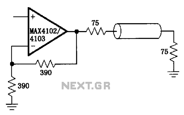
The MAX4102/4103 serves as a video configuration and RF distribution amplifier. The signal input for the MAX4102/4103 undergoes amplification before being output. To minimize the reflection during the transfer process, it is essential to select a termination impedance that...
The objective is to enhance information transmission through the distribution of articles. For any issues related to article content, copyright, or other concerns, please reach out via email to [email protected] within 15 days. Prompt action will be taken to...
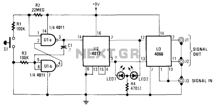
The A/B switch circuit comprises three integrated circuits (ICs) and several resistors. Two gates from a 4011 quad 2-input NAND gate (U1A and U1B) are configured as a monostable multivibrator. When switch SI is activated, it triggers a 4017...