
Video Switch Circuit Schematic Diagram
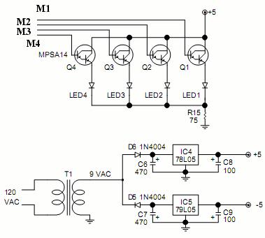
The video switcher circuit is designed to facilitate the selection of multiple video inputs for display on a single output monitor. The MAX454, a key component, functions as both a multiplexer and an amplifier, ensuring that video signals are processed with minimal degradation. It is important to maintain a well-planned signal path around the MAX454 to optimize performance. The inclusion of a ground plane between the signal channels is a recommended practice to reduce crosstalk and interference, which can adversely affect video quality.
The CD4017 decade counter serves as a sequencer that controls the activation of channel indicators, represented by LEDs (LED1-LED4). This sequencer operates by decoding a 2-bit binary signal, allowing for straightforward selection of the desired video channel. The outputs from the CD4017 not only indicate which channel is currently active but also facilitate the switching of the MAX454 multiplexer to the corresponding video input.
In designing the PCB for this circuit, it is essential to ensure that the MAX454 is soldered directly to the board to maintain signal integrity and reduce the potential for noise introduction. Proper layout techniques, including the use of ground planes and careful routing of signal traces, will enhance the overall performance of the video switcher circuit, making it suitable for applications requiring reliable video source selection.Video switcher circuit is needed to display more than one display in one monitor. Take a look at below circuit schematic : MAX454 is the core of this video. It is a video multiplexer-amplifier assembled by MAXIM Semiconductor. Pay attention when designing the video signal path around this chip. Track of ground plane can be inserted between video signal channels to prevent crosstalk and noise interference. The chip should directly soldered to the PCB. A CD4017 sequencer which drive the channel indicators (LED1-LED4) can be seen here. The output will decode 2 bit binary data by D1. D4 to address MAX454 multiplexer. The output of this sequencer also drives the indicators. 🔗 External reference
Related Circuits
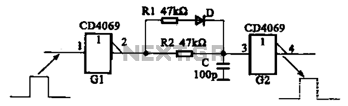
The inverter circuit using CD4069 is configured with a delay and width adjustment. When the output of the inverter (G1) is high, the capacitor (C) charges through resistor (R1) and diode (D). The voltage across capacitor C quickly reaches...
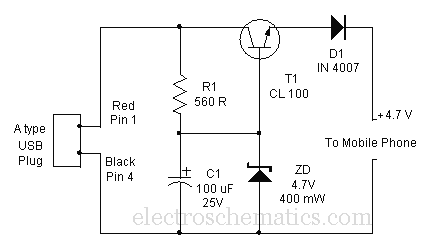
Comprehensive information about a USB cellphone charger circuit is available for learning and downloading online. The USB cellphone charger circuit is designed to convert AC mains voltage into a stable DC voltage suitable for charging mobile devices. This circuit typically...
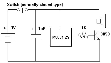
The M8031 circuit features an integrated RC oscillator and digital envelope circuits, which minimize the need for external components. It produces a sound that mimics a mechanical ding-dong. The M8031 operates with a low input voltage range of 1.3...
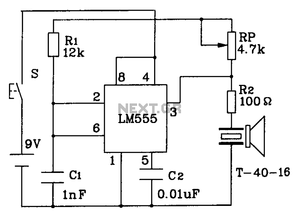
The circuit described is a 555 ultrasonic transmitter constructed to emit ultrasonic signals at a frequency of 40 kHz. It operates by generating oscillating pulse outputs from a 555 timer (specifically the T-40-16 model). The circuit is designed to...
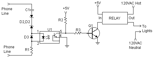
The inquiry pertains to the connection of lights that flash when a phone rings. This feature is particularly beneficial in noisy environments, such as workshops, where hearing the phone may be difficult. A device designed for this purpose is...
I designed up this circuit board because of a request from a visitor to my website. I also assemble the circuit board to verify the board was correct. It does work, very nicely, but I have no way to...