
Oatley K272 JAN 6418 Valve (Tube) Preamplifier / Headphone Amp Kit
] A photograph of the Oatley Electronics tube preamplifier kit is shown below. The kit is complete but comes with very ordinary (generic) components which is not surprising considering the very low cost of the kit. The printed circuit board (PCB) is plated through, dual layered, solder masked and screen printed. The kit can be run off a 9V battery which makes this a safe and ideal kit for those who are new to electronics.
Some of you will likely be turned off by the very low cost of this kit. Before you pass judgment on this little kit, do note that Audio-Technica uses a JAN 6418 sub-miniature tube in its model AT3060 condenser microphone which sells for about $600US. Music professionals often describe this microphone as having a warm classic tube sound. These 6418 valves look like small Christmas Tree lights. Hard to believe that they are actually pentodes. The USA made Raytheon JAN6418 sub-miniature valves are low power consumption pentodes that are used as triodes in the circuit.
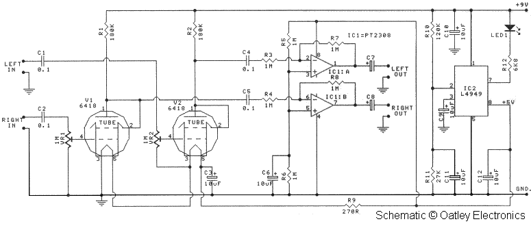
I built one straight out of the packet and loved the sound so much I decided to get a few more of the kits and try some builds using better parts. It took just over an hour to put the kit together. The 6418 tube filaments are 1. 2V and draw just 10mA. You can barely see the tubes glowing in a dark room and the are just slightly warm to the touch. From a single 9V battery the entire preamplifier draws just 12mA. For a longer run time I used two 9V lithium batteries in parallel. The 9V supply is the B+ (or laughingly HT+) while a small 5V regulator chip (L4949) and 270R resistor feed the filaments which are wired in series.
The second stage is a low distortion CMOS headphone driver IC (PT2308) that is set to unity so the preamp can drive both high and low impedance loads including headphones. The gain of the circuit is adjustable from 0 to 7 times and can be increased further if required. A LED lights for the first few seconds when the device is turned on to show the device is on then it only re-lights when the battery voltage falls below 6.
8V. The schematic is shown in Figure 1. Please note that this circuit is © Oatley Electronics and permission to host the schematic on this site has been provided by Oatley Electronics. For the next build I swapped the all carbon resistors with metal film types, the 0. 1uf MKT input and inter-stage capacitors were replaced with 0. 47uF polypropylene film types, the PT2308 headphone driver chip was swapped out for a Burr-Brown OPA2134 op-amp, and the 220uF electrolytic output capacitors were also replaced.
The valves are extremely microphonic and will "ring" if they are struck so rubber grommets are used to help damp the tubes. This does work and removes all audible noise from mechanical vibrations. With the original PT2308 IC the kit is a capable headphone driver. The PT2308 has only slightly higher distortion figures than the OPA2134 but can drive more demanding loads such as 32 ohm headphones.
Because I am using this build strictly as a preamp (feeding a valve power amp) the OPA2134 is a better choice. For the gain control I used are two PCB mountable potentiometers (pots). The kit comes with 1M trim pots which mount direct to the PCB which will accommodate either vertical or horizontal mounting trim pots.
The trim pots would work for me as my Oppo 980H (modified by Custom Analogue) CD/DVD player has a volume control but there are times when twisting a knob to get desired volume level has its advantages. So I used two small knobs extending out the front of the enclosure to facilitate gain setting. They are not intended t 🔗 External reference
Related Circuits
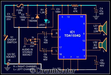
The circuit diagram illustrates a robust stereo amplifier capable of delivering 22W of power. It is based on the widely used single-chip audio power amplifier TDA1554Q (IC1), which is configured as two 22W stereo bridge amplifiers. While listening to...
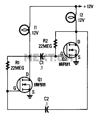
The circuit consists of two power FETs configured as a simple astable multivibrator to alternately switch two lamps on and off. The resistor-capacitor (RC) values set the flash rate to approximately 1/3 Hz. By varying either the resistor or...
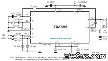
The IC TDA7295 is a monolithic integrated circuit designed for use as an audio class AB amplifier in high-fidelity applications, including home theaters and high-end televisions. The TDA7295 is a versatile audio amplifier that delivers high-quality sound reproduction, making it...
A Class A Class AB amplifier rated 100 Watts when driving a 4 ohm loudspeaker. This circuit developed out of my 30+ years of JLH class-A based investigations. The original simple 1969 JLH class-A design provided excellent first cycle accuracy...
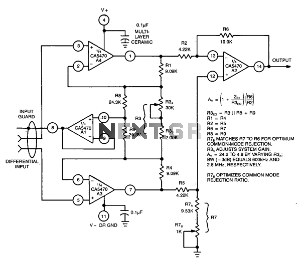
This circuit utilizes a CA5470 quad microprocessor BiMOS-E operational amplifier. Amplifiers A1 and A2 are configured as a cross-coupled differential input and differential output preamplifier stage, while A3 is responsible for input guard-banding. Additionally, amplifier A4 converts the differential...
This is a schematic diagram of a general-purpose audio frequency (AF) amplifier circuit. The circuit employs inexpensive 1/4-W resistors, as high precision is not required. The general-purpose audio frequency (AF) amplifier circuit is designed to amplify audio signals for various...
Warning: include(partials/cookie-banner.php): Failed to open stream: Permission denied in /var/www/html/nextgr/view-circuit.php on line 713
Warning: include(): Failed opening 'partials/cookie-banner.php' for inclusion (include_path='.:/usr/share/php') in /var/www/html/nextgr/view-circuit.php on line 713