
22W Mobile Car Stereo Power Amplifier PCB
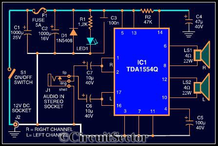
The TDA1554Q integrated circuit is a versatile audio amplifier solution, particularly suitable for automotive applications due to its compact design and efficient power handling. The device operates in class-B mode, which allows for a good balance between sound quality and power efficiency. The configuration of the TDA1554Q as a bridge amplifier is crucial for maximizing output power; by utilizing two of the four internal amplifiers, the circuit can effectively double the output power to each channel, thus achieving the desired 22W rating.
The setup requires a 12V power supply, which is standard in most vehicles, ensuring compatibility and ease of installation. The RCA socket J2 serves as the power connection, allowing for straightforward integration into the car's electrical system. The audio input socket J1 is designed to accept a standard 3.5mm audio jack, making it easy to connect a wide range of mobile devices without the need for specialized connectors or adapters.
For optimal performance, the output stage of the amplifier is connected to two speakers (LS1 and LS2), which should be selected based on their impedance and power handling capabilities to match the amplifier's output. Proper placement of the speakers within the vehicle is essential for achieving an immersive audio experience, with consideration given to the acoustics of the car's interior.
In summary, this stereo amplifier circuit utilizing the TDA1554Q provides an effective solution for enhancing audio playback from mobile devices in a vehicle. Its straightforward design, combined with the efficiency of the integrated amplifier, makes it an excellent choice for users seeking to improve their in-car listening experience without the complexities of traditional car audio systems.The circuit diagram shows a powerful stereo amplifier which can deliver a power of 22W. It is built around popular single-chip audio power amplifier TDA1554Q (IC1). Here it is configured as two 22W stereo bridge amplifiers. Listening to songs stored in mobile phone while driving is dangerous. It`s also against laws. But you can use your mobile phone as a stereo music source and it requires amplification to drive speakers. Also This does away with the need of a sophisticated in-dash car music system. The TDA1554Q is an integrated class-B power amplifier in a 17-lead single-in-line (SIL) plastic power package. The IC contains four identical 11W amplifiers with differential input stages and can be used as abridge amplifier that merges two amps to give 22W each channel.
The gain of each amplifier is fixed at 20 dB. The amplifier is powered from the 12V car battery through RCA socket J2. Connect stereo sound signal from the 3. 5mm headset socket of the mobile phone to audio input socket J1. When you play the music from your mobile, TDA1554Q amplifies the input. The output of IC1 is fed to speakers LS1 and LS2 fitted at a suitable place in your car. The other circuit elements are quite common for all amplifiers. 🔗 External reference
Related Circuits
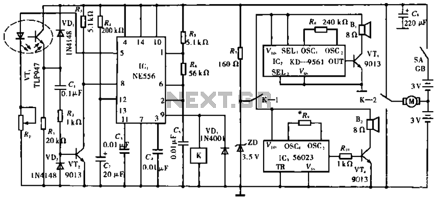
The circuit operates with VT1, which is an integrated infrared receiver, utilizing a red-emitting diode for perimeter triode reception. IC1 (NE556) functions as a dual timer, with R5, R6, and C5 forming an oscillation circuit that generates a frequency...
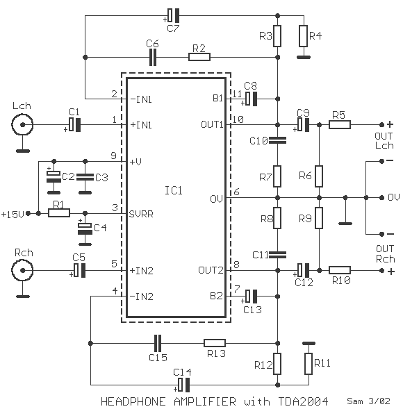
The provided description pertains to an operational amplifier (opamp) of medium power, specifically configured to amplify headphone signals and drive low loads. The opamp essentially comprises two amplifiers. The voltage gain for each amplifier is set at 40dB, determined by...

This simple mobile voltage regulator circuit may save your two-meter or CB transceiver if the voltage regulator fails. The 2N3055 should be heat-sinked if the current drawn by the rig exceeds 2 A during transmission. This circuit will do...
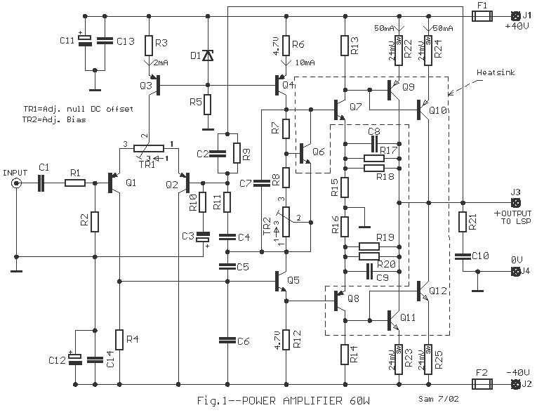
In the circuit exists a simple power amplifier 60W in the 8 ohm and 80W in the 4 ohm, with components that sure exist in big quantities. It can be used in home cinema systems or in other uses....
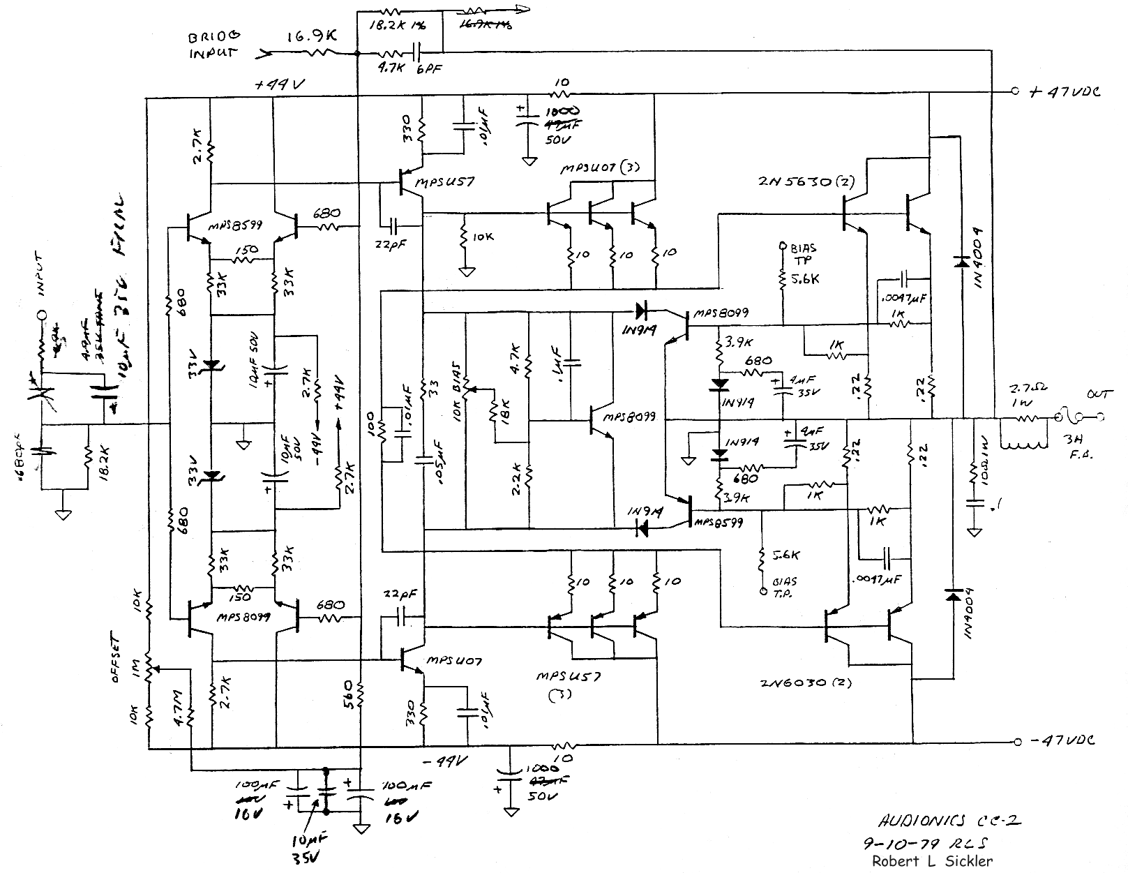
The Audionics CC-2 is named after Cliff Moulton, the chief engineer, and Charles Wood, the president of Audionics. However, the true designer of the amplifier is Bob Sickler, whose initials, "RLS," appear on the schematics. Following Bob's passing in...
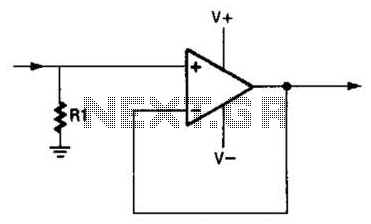
An operational amplifier (op amp) can function as a unity gain amplifier by connecting its output to its inverting input as illustrated. The load resistance (Rl) should be sufficiently low to prevent the op amp's bias current from introducing...
Warning: include(partials/cookie-banner.php): Failed to open stream: Permission denied in /var/www/html/nextgr/view-circuit.php on line 713
Warning: include(): Failed opening 'partials/cookie-banner.php' for inclusion (include_path='.:/usr/share/php') in /var/www/html/nextgr/view-circuit.php on line 713