
Octave Equalizer Circuit
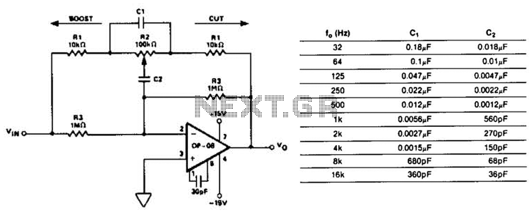
The octave equalizer circuit is designed to enhance audio signals by allowing specific frequency bands to be adjusted independently. Each section of the equalizer corresponds to a specific octave band, enabling precise control over the audio spectrum. The operational amplifier used in this design, the OP-08, exhibits low input bias current, which is advantageous for maintaining signal integrity and minimizing distortion.
The capacitors C1 and C2 are crucial for determining the center frequencies of each octave band. By selecting appropriate values for these capacitors, the circuit can be tuned to target specific frequencies, thus allowing the user to boost or cut audio levels as desired. The resistor R2 acts as a variable element in the circuit, enabling the adjustment of gain and attenuation. When R2 is positioned to allow maximum resistance, the circuit can achieve a 12 dB cut, while a lower resistance setting will provide a 12 dB boost.
The ability to scale resistors by a factor of 10 is particularly beneficial for low-frequency applications. This scaling reduces the necessary capacitance values, which can help in minimizing the physical size of the components and improving the overall performance of the circuit. Additionally, the low supply current requirement of 6 mA for 10 sections makes this design efficient, allowing it to be integrated into various audio systems without significant power consumption.
Overall, this octave equalizer circuit provides a versatile solution for audio signal processing, enabling users to tailor sound characteristics to their preferences while maintaining high fidelity and low power consumption. This circuit is one section of an octave equalizer used in audio systems. The table shows the values of CI and C2 that are needed to achieve the given center frequencies. This circuit is capable of 12 dB boost or cut, as determined by the position of R2. Because of the low input bias current of the OP-08, the resistors could be scaled up by a factor of 10, and thereby reduce the values of CI and C2 at the low-frequency end. In addition, 10 sections will only draw a combined supply current of 6 mA maximum. 🔗 External reference
Related Circuits
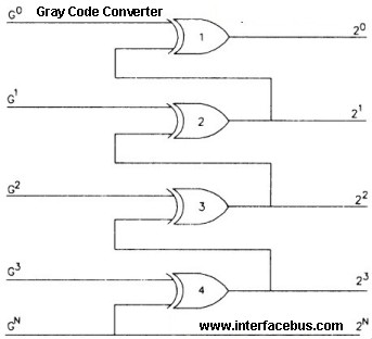
Gray Code is a positional binary number notation where any two numbers differing by one are represented by expressions that are identical except in one position, differing by only a single unit in that place. This code consists of...
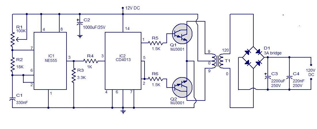
This is a simple circuit designed to convert 12V DC to 120V DC. The circuit comprises two main phases: the inverter stage and the rectifier and filter stage. The NE555 integrated circuit (IC1) is configured as an astable multivibrator,...
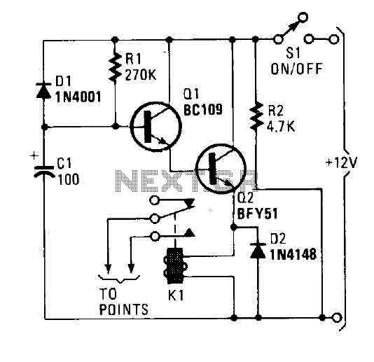
A flip of 51 activates the system. Power for the circuit is derived from the ignition switch, and the circuit receives no power until the ignition switch is closed. When the camera is powered on, capacitor C1 is charged,...
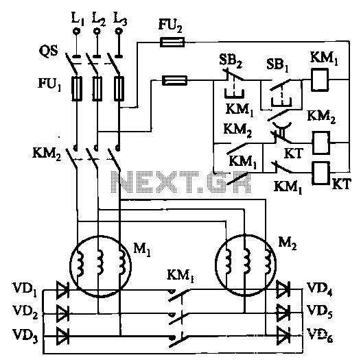
The circuit depicted in Figure 3-157 is designed for motors with a capacity of no more than 11 kW, requiring precise stopping capabilities. Upon shutdown, contact KMi releases, and the motor stator windings are configured into a three-phase rectifier...
The circuit is designed to set a delay time based on the voltage Us and the resistor R. In this configuration, S1 acts as the discharge switch for capacitor C. When switch S1 is closed, the stored charge in...
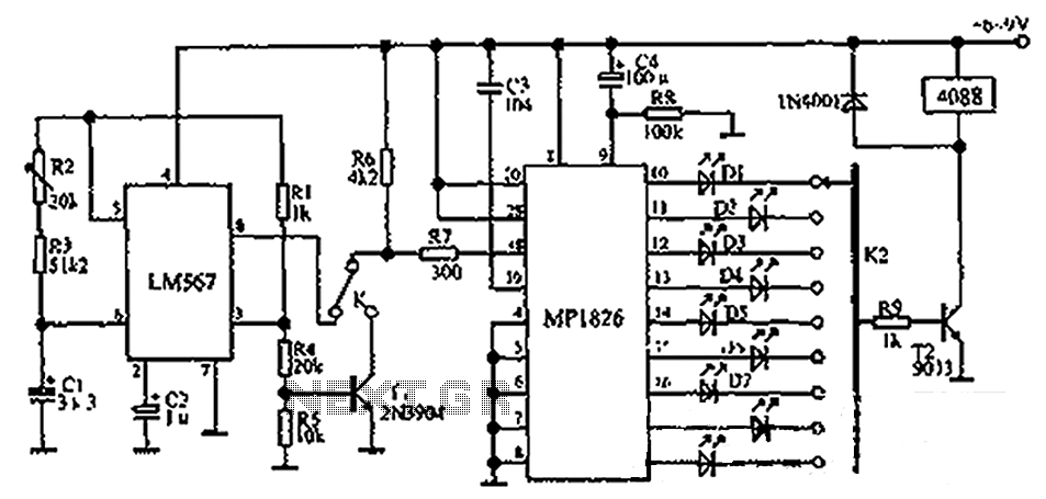
The circuit illustrated in the figure incorporates the MP1826 as a multi-stage divider. The LM567 serves as the frequency demodulation component, functioning as a dual-band oscillator that generates the desired low-frequency pulse from the MP1826. The oscillation center frequency...