
Off line Telephone tester

The offline telephone tester circuit is designed to evaluate the functionality of telephone instruments independently of an active telephone line. This is particularly useful for troubleshooting and verifying the operational status of phones in environments where a telephone line is not accessible or available.
The core components of the circuit typically include a power source, a series of resistors, capacitors, and a basic audio signal generator. The power source can be a battery or a DC power supply that provides the necessary voltage for the circuit to operate. The audio signal generator produces a tone that simulates the ringing or dialing sound of an actual phone line, allowing the user to test the audio output of the telephone instrument.
Resistors are strategically placed to limit current and protect sensitive components within the circuit. Capacitors may be used to filter signals and stabilize the power supply, ensuring that the audio signal remains clear and free of noise.
The circuit may also incorporate a simple LED indicator to provide visual feedback when the telephone instrument is connected and operational. This can help users quickly identify whether the phone is functioning properly or if further troubleshooting is required.
Overall, the offline telephone tester circuit is a valuable tool for technicians and hobbyists alike, enabling efficient testing of telephone instruments without reliance on external telephone lines. Its simplicity and effectiveness make it an essential addition to any electronics toolkit.Off line Telephone tester. Here is a circuit of an off-line telephone tester which does not require any telephone line for testing a telephone instrument. The circuit is so simple that. 🔗 External reference
Related Circuits
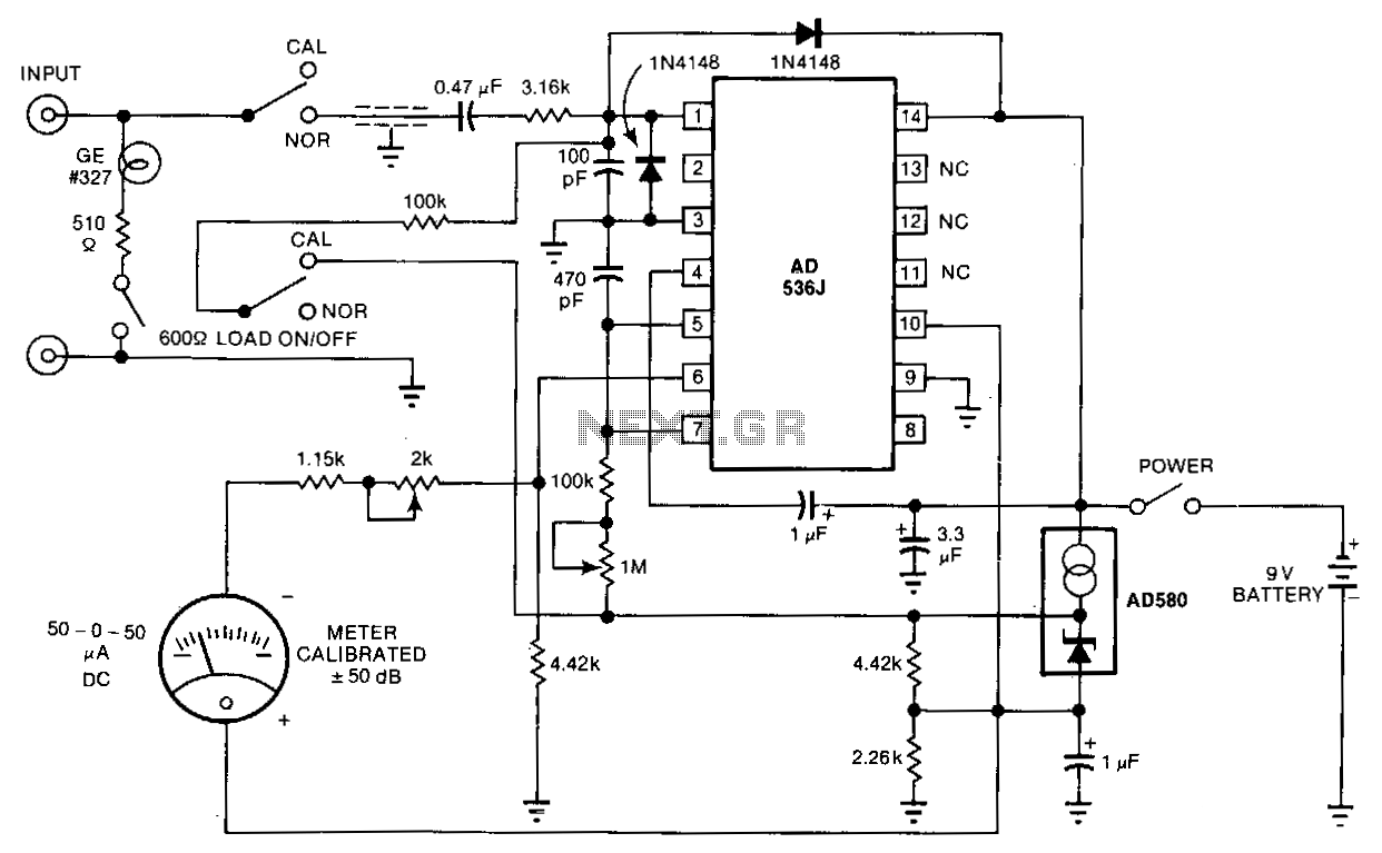
The telephone-line decibel meter and line-voltage sensor enables accurate monitoring and adjustment of telephone sound levels. The 600-ohm resistor appropriately terminates the line. The power consumption from the 9-volt battery is 2 mA, and the meter offers a ±30...
Commonly used 3-pin linear voltage regulators, such as the LM317, cannot handle input voltages exceeding approximately 30V. The LR8A from Supertex Inc is a new adjustable three-pin regulator capable of accepting input voltages up to 450V and supplying an...
It uses old pulse dial handsets and replaces the AC bell set with a 9 volt DC buzzer. The whole circuit runs from a 12 volt regulated DC supply and is suitable for short term battery operation (eg: Gel...
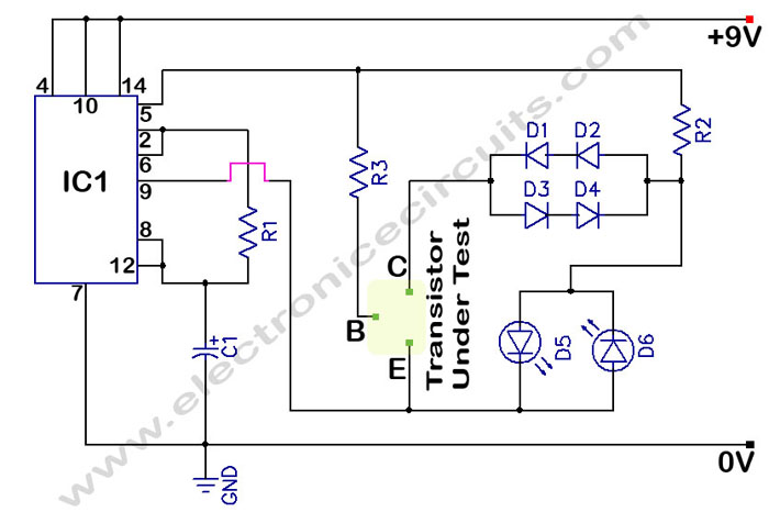
In a circuit transistor tester schematic, there is a circuit that can indicate the condition of a transistor using two LEDs. A good NPN transistor... The circuit transistor tester is designed to evaluate the functionality of both NPN and PNP...

The National Semiconductor LMV225 is a linear RF power meter integrated circuit (IC) in a surface-mount device (SMD) package. It operates over a frequency range of 450 MHz to 2000 MHz. The LMV225 is designed for precise measurement of radio...
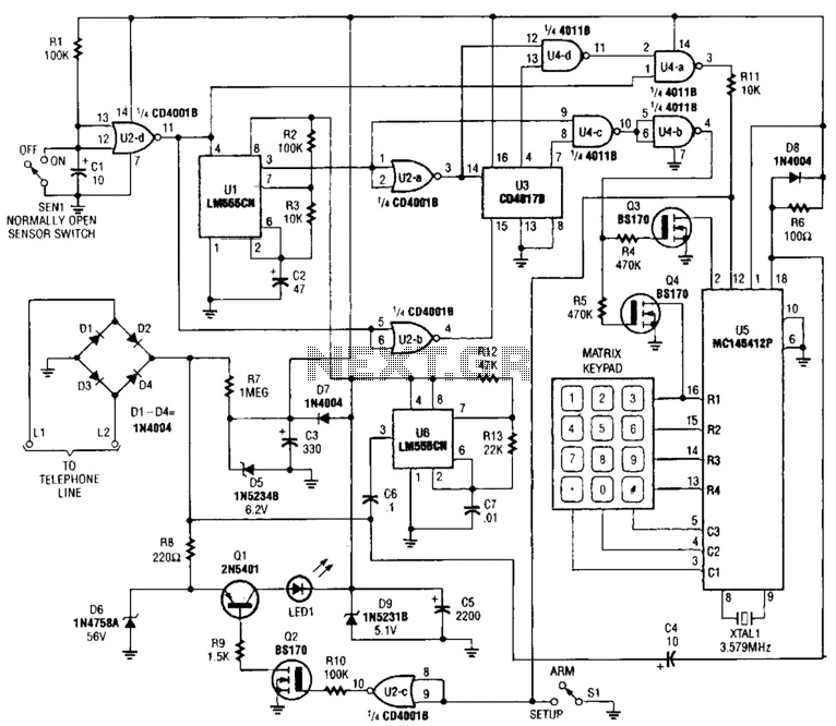
This system will alert individuals by automatically dialing a programmed phone number. It operates by monitoring an open-loop or closed-loop sensor switch located in the protected area. When the sensor detects an issue, such as a break-in, fire, heating...