
One 2N2222 Transistor Code Lock
The circuit operates by utilizing a transistor as a switch to control the relay. When a specific input signal, typically a voltage from a keypad or another control mechanism, is applied to the base of the transistor, it allows current to flow from the collector to the emitter. This action energizes the relay coil, causing the relay to switch its contacts and thereby control a connected load, such as a light or an electronic device.
In this configuration, the transistor is usually an NPN type, which is common for switching applications. The base of the transistor is connected to a resistor to limit the current flowing into it, ensuring that the transistor operates within safe parameters. The relay, which acts as the load, is designed to handle higher currents than the transistor can manage directly, allowing for the control of larger devices.
The code lock functionality can be implemented by integrating a keypad or a series of switches that provide the necessary input signal to the transistor. A microcontroller can also be employed to decode the input and provide additional features, such as timed access or multiple user codes.
Overall, this simple transistor switch circuit with a relay provides an effective means of controlling electrical devices based on specific input conditions, making it a versatile solution for various electronic locking applications.The circuit is nothing but a simple transistor switch with a relay at its collector as load. The simplest electronic code lock circuit uses one .. 🔗 External reference
Related Circuits

The circuit utilizes a 555 timer IC to create a lighting group delay effect, as illustrated in Figure 2-46. It consists of the 555 IC along with a resistor and capacitor configuration that establishes the delay. The circuit remains...
The widespread application of Surface Mount Technology (SMT) in products such as computers, network communications, consumer electronics, and automotive electronics has led to increasingly complex, high-precision, and multifunctional electronic assemblies. Accurate testing techniques can enhance manufacturing efficiency and ensure...
A DC-to-DC step-up converter is typically implemented using a transformer, which converts DC voltage to AC voltage, steps it up with the transformer, and then rectifies and filters the output to achieve a higher DC voltage. However, a voltage...
The transmitter for the wireless headphones is built around a CD4046 CMOS phase-locked loop, coupled with a driver transistor, and a pair of infrared LEDs. More: Although the CD4046 is comprised of two phase comparators, a voltage-controlled oscillator (or...
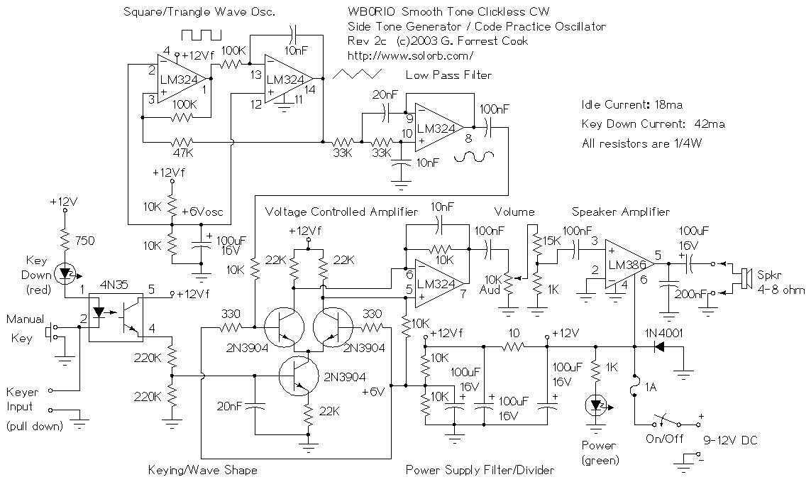
This circuit is about as good as it gets for generating morse code tones. It may be used as a code practice oscillator, a tone generator for a keyer, a sidetone oscillator for a CW transmitter or an audio...
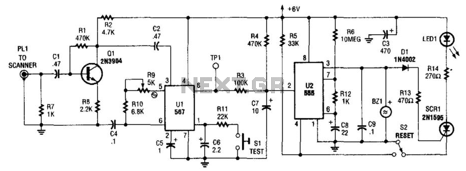
This circuit detects the 1050-Hz tone transmitted by NOAA (National Oceanic and Atmospheric Administration) weather radio stations, which operate within the frequency range of 162.40 to 162.55 MHz. The tone is emitted for several seconds. Q1 functions as an...