
Transformerless Voltage Booster Circuit: A DC-DC Step-Up Switching Regulator Using Transistors
The DC-to-DC step-up converter operates on the principle of energy transfer through an inductor in a switching configuration. The circuit typically includes a power source, an inductor, a switching transistor, a diode, and a load. When the switching transistor is turned on, current flows through the inductor, storing energy in the magnetic field. Once the transistor is turned off, the inductor releases its stored energy, and the resulting voltage spike is directed to the output through the diode, effectively increasing the voltage.
The feedback mechanism involving the zener diode plays a crucial role in regulating the output voltage. The zener diode is connected to the output and provides a reference voltage. As the output voltage rises above the desired level, the zener conducts, providing feedback to the control circuit that adjusts the switching frequency of the transistors. This feedback loop ensures that the output voltage remains stable under varying load conditions.
The Schmitt trigger configuration formed by transistors Q1, Q2, and Q3 ensures a clean transition in the switching operation, minimizing voltage spikes and oscillations that could adversely affect performance. The choice of the 2N3053 transistor as the main switching element is due to its ability to handle higher currents, making it suitable for applications where load demands can vary significantly.
For practical implementation, the circuit layout should be optimized for minimal inductance and resistance in the connections to enhance efficiency. Proper heat dissipation techniques should also be employed, particularly for the 2N3053 transistor, to prevent thermal overload. Additionally, selecting the appropriate inductor and diode is critical for achieving the desired performance specifications, such as efficiency and output power capacity.
In summary, this step-up converter design is a robust solution for applications requiring a higher voltage from a lower voltage source, particularly in automotive and portable electronic devices. Its reliance on discrete components allows for customization and flexibility in design, making it an attractive option for engineers and hobbyists alike.A DC-to-DC step-up converter is traditionally implemented using transformer, working by converting the DC voltage to AC Voltage, step-up it using transformer, then rectify and filter the transformer`s output to get a higher DC voltage. Using a switching method, we can step-up a voltage without a transformer. We just need an inductor which is drive n by a switching transistor to boost the voltage. This circuit store the electric energy in an inductor before it is added to the input voltage, so this circuit is different than capacitor charge pump that store the electric energy using a capacitor. The most interesting this is that circuit use a discrete components: no integrated chip is required, only few transistors with few passive components.
Because the switching topology is a boost converter, this circuit cannot be operated as step-down regulator, so the output will always be higher than the input. The voltage output is depend on the load because the feedback mechanism, through the zener diode, will maintain the output at about 14 volt, regardless the voltage input variation and load current variation.
The current from the voltage divider will flow through the zener diode if the output goes higher than the nominal value, and this condition will stop the oscillator built around the 2N3904 transistors. Stopping the oscillator will drop the output voltage and thus maintain the required voltage level at the output.
This transistors (Q1, Q2, and Q3) form a Schmidt trigger that drive the final transistor Q4 (the switching transistor 2N3053 ). This circuit is suitable for battery booster, if you need to run your 12 volt equipments on your old car that provide only a 6V supply from the battery.
The output of this voltage doubler can be adjusted by changing the voltage divider, or for easier adjustment, you can replace the 4, 7K resistor with a 5K potentiometer. Using a good inductor (low resistance), you can achieve up to 80% efficiency, and up to 2 Watt power can be delivered to the load.
For the main diode, you can use a 3 Ampere Schottky diode 1N5822. [Circuit`s schematic diagram source: Bill Bowden`s circuit collection] 🔗 External reference
Related Circuits
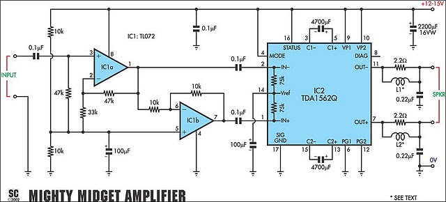
It is based on a Philips class-H audio amplifier integrated circuit and can deliver 36W RMS or 70W music power, all from a 13.8V supply. The new Mighty Midget Amplifier can produce approximately 36W RMS continuously into a 4-ohm...
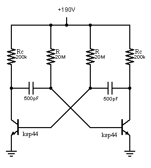
An oscillator is being developed to operate within the 200V range, targeting a frequency of approximately 1 kHz while minimizing current consumption. Initial testing has commenced. The design of a high-voltage oscillator capable of operating at 200V and generating a...
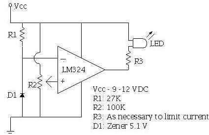
An ECU must have a way to monitor battery voltage. Here is a simple op-amp based circuit which will illuminate the LED when the battery voltage drops to a certain level. The turn-on point is set with R2. You...
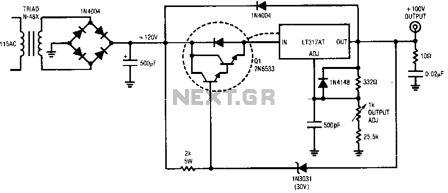
The regulator provides a 100 V output at 100 mA and can withstand shorts to ground. Even at a 100 V output, the LT317A operates in normal mode, maintaining a 1.2 V difference between its output and adjustment pin....
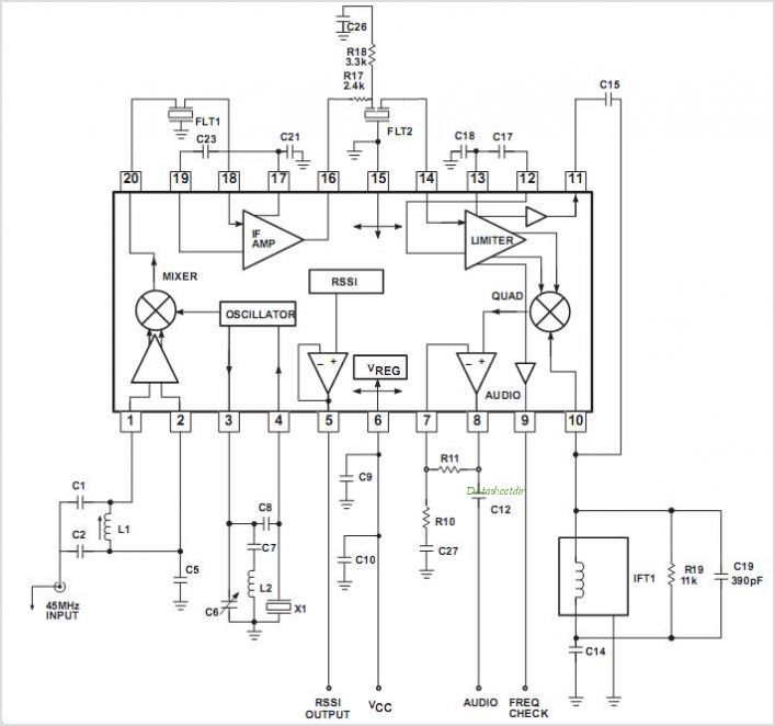
The SA608 is a low-voltage, high-performance monolithic FM intermediate frequency (IF) system that includes a mixer, oscillator, two limiting intermediate frequency amplifiers, a quadrature detector, a logarithmic received signal strength indicator (RSSI), a voltage regulator, and audio and RSSI...
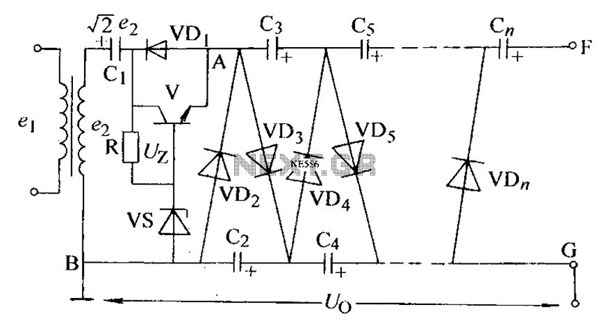
The circuit is an adjustable output voltage regulator type rectifier. It allows for obtaining peak voltage at odd multiples when the output voltage is taken from the circuit feedback (FB). Additionally, the lower point of the capacitor (CB) can...
Warning: include(partials/cookie-banner.php): Failed to open stream: Permission denied in /var/www/html/nextgr/view-circuit.php on line 713
Warning: include(): Failed opening 'partials/cookie-banner.php' for inclusion (include_path='.:/usr/share/php') in /var/www/html/nextgr/view-circuit.php on line 713