
One Direction Motion Sensor
The one-direction motion sensor circuit utilizes two phototransistors, Q1 and Q2, strategically placed to monitor a designated path. Q1 is positioned to detect the initial obstruction of light as an object approaches, while Q2 is placed downstream to confirm the direction of movement. When an object passes through the detection zone, it first blocks the light at Q1, causing a high output signal at point A. This signal is essential as it enables the circuit to register that an object is entering the detection area.
As the object continues moving toward Q2, it subsequently blocks the light at Q2. The interruption at Q2 triggers the differentiator capacitor (0.4 µF), which generates a short pulse at point C. This pulse is critical for the circuit's functionality, as it signifies that an object has passed through the detection zone in the intended direction. The circuit is designed such that the pulse at point C will only result in a high output if the signal from Q1 is also high, thus ensuring that only objects moving from Q1 to Q2 are detected.
The output of the circuit can be connected to various devices, such as alarms, counters, or automated gates, to perform specific actions based on the detected motion. This configuration allows for precise control and monitoring of movement in a designated area, making it suitable for applications in security systems, automated access control, and traffic monitoring. The simplicity of the circuit design, combined with the reliability of the phototransistors, ensures effective operation in various environments.This is a one direction motion sensor circuit. This motion sensor circuit is used to detects an object passing in one direction, ignoring an object that going to opposite way. This circuit uses two sensors to identify the movement only in one direction. The basic principle of this circuit is simple, where one sensor is used to generate a short pu lse, and the other sensor is used to block of turn of the gate. The phototransitors give high output on their collectors when there is an object blocking the light. By a 0. 4uF differentiator capacitor, the interruption of light at Q2 sensor will produce short pulse at point C. But this short pulse will only appear at the output if a high signal appears at A. This condition will be satisfied if the light to Q1 is blocked by the object when the object is passing through Q2, means that the direction should be from Q1 to Q2.
Here is the schematic diagram of the circuit: 🔗 External reference
Related Circuits
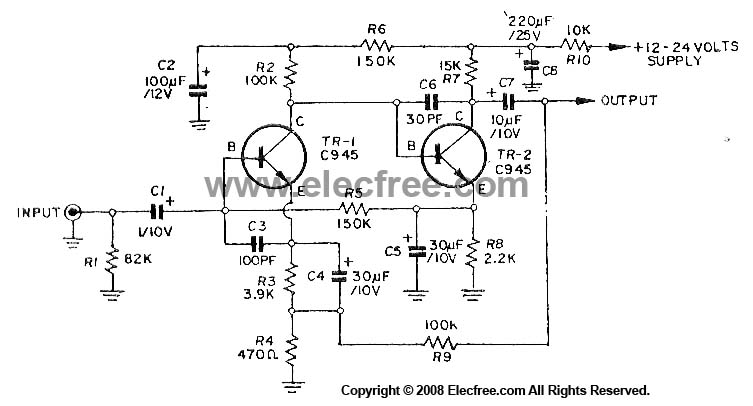
This circuit utilizes three transistors (2SC945, 2C1815, or 2SC828) as the primary components, functioning as a typical low-noise transistor amplifier. It offers a gain of approximately 200 to 300 times and has a frequency response ranging from 50Hz to...
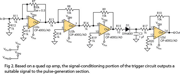
This version of the trigger circuit for the stop-motion camera system utilizes an electret microphone for sonic input, although it can be replaced with an LED and photodiode pair for optical triggering. A recent home-built project involved constructing a...
Due to their speed, accuracy, effectiveness, and cost-efficiency, infrared (IR) digital thermometers have supplanted traditional mercury thermometers. An ear digital thermometer utilizes a thermopile sensor to measure the infrared heat emitted by the eardrum, which correlates with the temperature...
It is a relatively simple circuit, with which we can have optical and sound clue, when we have telephone ring in the line of telephone. The calls in the line, are changed in pulses of frequency 400 HZ from...
The water resource is being transformed into a valuable and rare commodity. Consequently, promoting water-saving irrigation has become a priority for countries worldwide to address the water resource crisis and achieve agricultural modernization. This text proposes a cipher scheme...
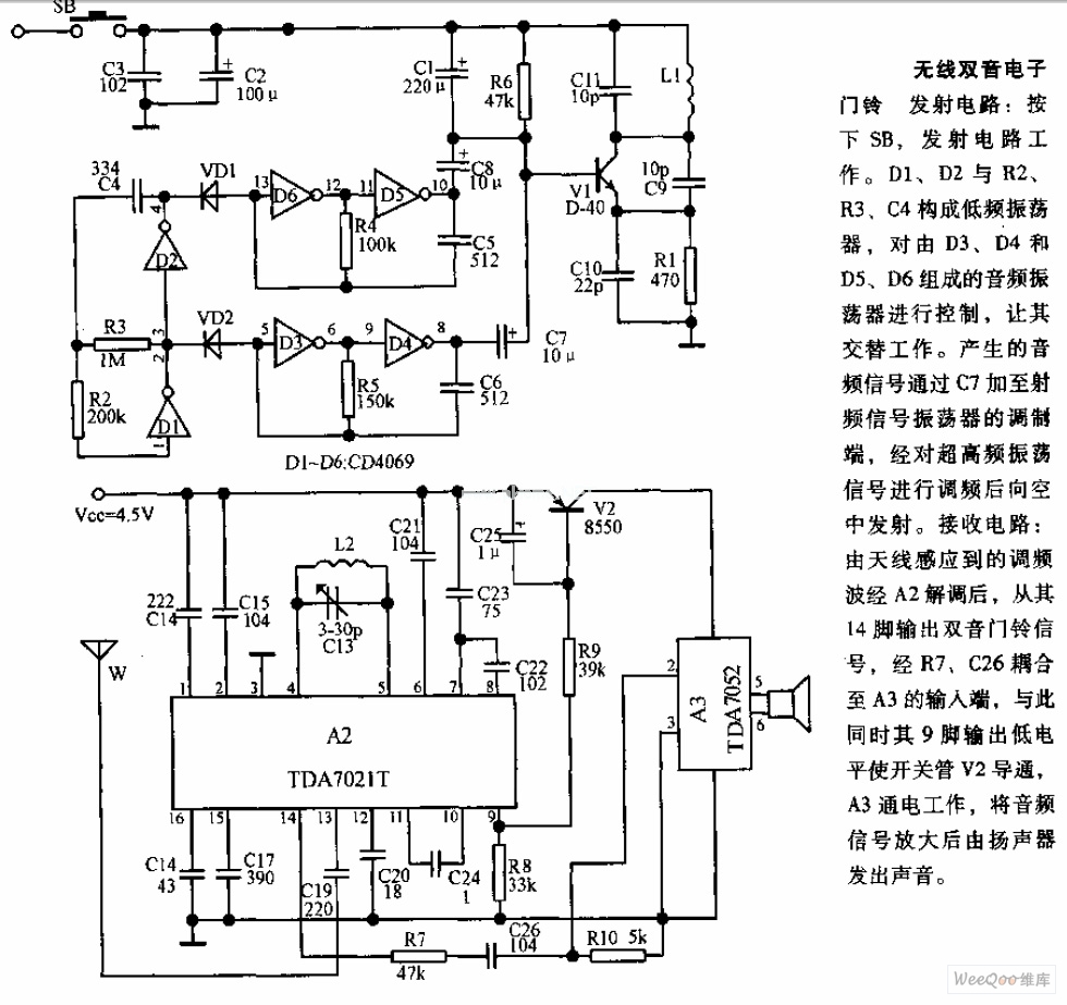
The transmitter circuit is activated by pressing the SB button. Components D1, D2, R2, R3, and C4 form a low-frequency oscillator that controls an audio oscillator made up of D3, D4, D5, and D6, allowing them to operate alternately....