
One Ic Capacitance Tester Circuit
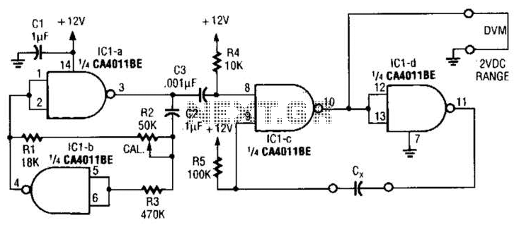
The capacitor matching circuit operates by utilizing a voltage divider or a similar configuration to produce a DC output voltage that reflects the capacitance of Cx. The fundamental principle relies on the relationship between capacitance and voltage, where variations in capacitance will result in corresponding changes in the output voltage.
To implement this circuit, a suitable operational amplifier (op-amp) can be used to amplify the voltage across Cx, ensuring that the output voltage is within a measurable range. A resistor network may be incorporated to set the gain of the op-amp and to provide a reference voltage, which can be adjusted to calibrate the circuit for different capacitance values.
For capacitors below 0.01 microfarads, the values of the resistors and the feedback configuration of the op-amp may need to be modified to ensure accurate readings. Conversely, for capacitors above this range, the circuit can be adjusted by changing the resistor values or by incorporating additional stages of amplification to maintain linearity and precision in the output voltage.
In practical applications, this circuit can be utilized in testing environments where precise capacitance matching is critical, such as in filter design, tuning circuits, or in quality control processes in manufacturing electronic components. The versatility of the circuit allows it to accommodate a wide range of capacitor values, making it a valuable tool for electronics engineers and technicians. This circuit can be used to match capacitors, etc. The dc output voltage is related to the capacitance values of Cx. The circuit values shown are for capacitors in the 0.01- order of magnitude, but they can be changed for lower or higher values. 🔗 External reference
Related Circuits
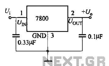
A fixed three-terminal integrated voltage regulator can be directly employed in various electronic devices as a voltage regulator. It features internal protections such as overcurrent protection, thermal protection, and safe operating area protection, making the circuit easy to use,...
The ATMEL AVR programmer operates with the Windows program "Ponyprog," which is compatible with Windows 95, 98, and XP. The ATMEL AVR programmer is a device designed for programming AVR microcontrollers. It interfaces with the microcontroller through the ISP (In-System...
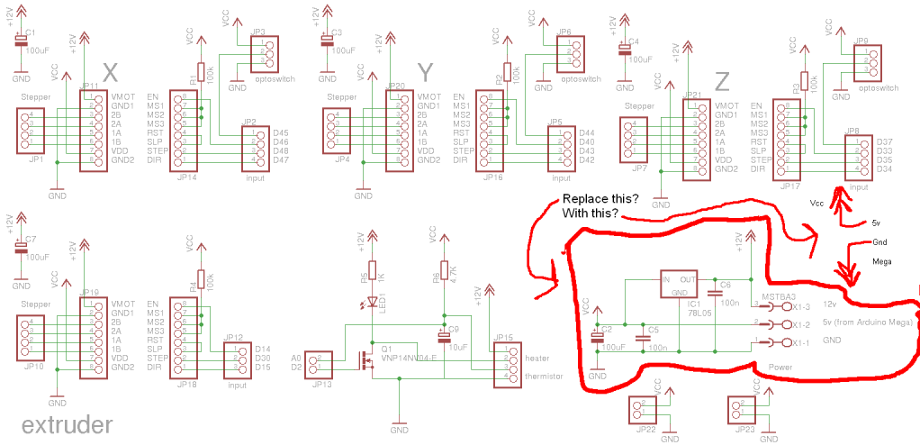
Preparing to assemble Adrian's Pololu stepper driver circuit has raised a question. He indicates that if using 5V from the Arduino Mega, the 78L05 voltage regulator should be omitted. This is a positive development, although there is an incorrect...
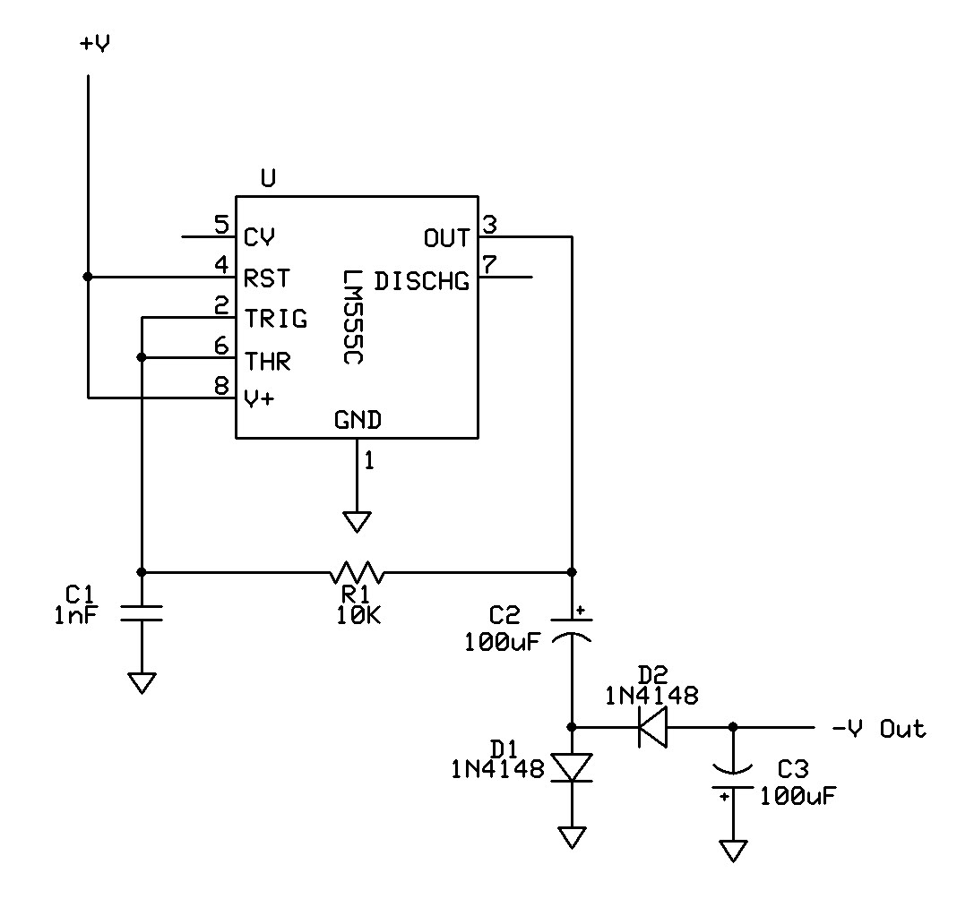
Can a 555 negative supply circuit, like the one below I pulled from another schematic, supply enough negative voltage to an LM324 and an AD736JN? The 555 timer integrated circuit can be configured to generate a negative voltage supply,...
This is an enhanced infrared (IR) remote control extender circuit that exhibits high noise immunity, resistance to ambient and reflected light, and an extended operational range of approximately 7 meters between the remote control and the extender circuit. It...
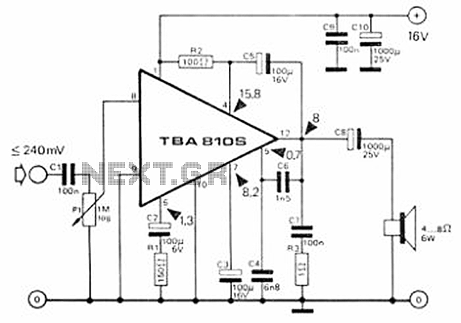
This circuit is a 7 Watt audio amplifier that is simple and easy to construct. It utilizes the TBA810 as the primary component, supported by a few passive components. The amplifier operates effectively, and the necessary kits and components...
Warning: include(partials/cookie-banner.php): Failed to open stream: Permission denied in /var/www/html/nextgr/view-circuit.php on line 713
Warning: include(): Failed opening 'partials/cookie-banner.php' for inclusion (include_path='.:/usr/share/php') in /var/www/html/nextgr/view-circuit.php on line 713