
Three-terminal voltage regulator integrated fixed a typical wiring circuit
The fixed three-terminal integrated voltage regulator serves as a crucial component in power supply circuits, providing stable output voltage levels for various electronic applications. The 7800 series regulators are designed to output a fixed positive voltage, while the 7900 series outputs a fixed negative voltage, allowing for versatile usage in both positive and negative voltage requirements.
The internal architecture of these regulators includes a voltage reference, an error amplifier, and a pass transistor. The voltage reference establishes a precise output voltage, while the error amplifier compares the output voltage to the reference voltage to ensure regulation. The pass transistor adjusts its resistance to maintain a constant output voltage despite variations in input voltage or load current, thus ensuring stable operation.
Overcurrent protection is implemented through a sensing mechanism that detects excessive current flowing through the regulator. If the current exceeds a predetermined threshold, the regulator will limit the output current to prevent damage. Thermal protection is also integrated, which shuts down the regulator if it overheats, thereby safeguarding the device from thermal damage. The safe operating area protection ensures that the regulator operates within its specified limits, preventing failure due to overvoltage or excessive power dissipation.
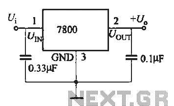
The compact three-terminal design simplifies integration into circuit boards, requiring only three connections: input, output, and ground. This configuration allows for easy installation and minimal space usage, making it ideal for a wide range of electronic devices, from simple consumer electronics to more complex industrial applications. The typical pinout for the 7800 and 7900 series regulators follows a standard layout, facilitating compatibility with existing designs and enhancing user convenience.
In summary, the fixed three-terminal integrated voltage regulator is an essential component for maintaining voltage stability in electronic circuits, characterized by its reliability, ease of use, and built-in protections against common electrical faults.Fixed three-terminal integrated voltage regulator can be directly used in various electronic devices as a voltage regulator. Since the internal set over current protection, thermal protection and safe operating area protection regulator circuit, the circuit easy to use, safe and reliable. A typical three- terminal integrated voltage regulator has fixed 7800 (positive voltage) and 7900 (negative regulator) two series.
Three-terminal voltage regulator integrated fixed wiring and typical shape shown in Figure
Related Circuits
This custom mod gives your computer the personality of KITT, the computerized car from Knight Rider TV fame. The project is a light display which imitates the dot in KITT's hood. It looks like the scanning eye of the...
The power supply has been simplified. Power transformers and rectifiers have been omitted, and some components from the MOSFET voltage regulator circuits have been removed, including 1N5242 zener diodes between the source and gate and 10k resistors in series...
The basic clock circuit is similar to the binary clock and uses 7 ICs to produce the 20 digital bits for 12 hour time, plus AM and PM. A standard watch crystal oscillator (32,768) is used as the time...
The voltage to be sampled is applied to the input of R2, a 100K linear taper potentiometer, while the other end of R2 is grounded. Consequently, the signal level that is sent to the buffering level shifter U1-A and...
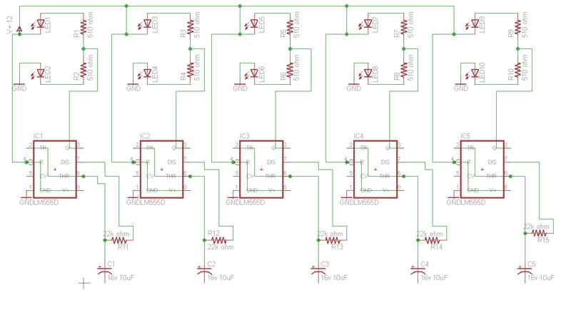
Build a circuit that will flash five pairs of LEDs at variable rates. To achieve this, a circuit utilizing five NE555 timers has been designed. Trim pots will be used to control the variable flash rate. Assistance is needed...
Construct a low-power FM transmitter using surface-mount devices (SMD) that can be received by a standard FM radio. The proposed low-power FM transmitter circuit utilizes surface-mount devices (SMD) to achieve compactness and efficiency. The primary components of the circuit include...
Warning: include(partials/cookie-banner.php): Failed to open stream: Permission denied in /var/www/html/nextgr/view-circuit.php on line 713
Warning: include(): Failed opening 'partials/cookie-banner.php' for inclusion (include_path='.:/usr/share/php') in /var/www/html/nextgr/view-circuit.php on line 713