
One simple second pulse source circuit

The described circuit operates as a relaxation oscillator, utilizing the single-junction transistor VTi to generate a time-dependent output. The resistor Ri plays a crucial role in setting the base biasing of VTi, while the capacitor C charges and discharges, creating oscillation. The potentiometer RP is integral to frequency adjustment; by varying its resistance, the charge and discharge time of capacitor C is modified, thereby altering the frequency of the oscillation. This allows for a flexible output pulse width, enabling the system to produce time base pulses between 0.1 seconds and 15 seconds.
The output from the relaxation oscillator is fed into the amplifier transistor VTz, which boosts the signal strength of the generated square wave pulse. This amplified output is critical for driving subsequent circuits, such as a time counter, ensuring that the pulse is adequately strong to be detected and processed. The overall design is efficient for applications requiring variable timing signals, making it suitable for timing applications in various electronic systems. The simplicity of the components involved allows for easy assembly and adjustment, making it a practical solution for generating controlled time intervals.It consists of single-junction transistor VTi, resistance Ri, potentiometer RP, capacitor C consisting of relaxation oscillator and amplifier transistor VTz. Adjustment potentiometer RP, can change the relaxation oscillation frequency to give 0. 1 ~ 15s time base pulse. After this pulse by VTz amplified output square wave pulse, as the time counter input signal.
Related Circuits

Most existing designs utilize direct switching of lights without any software control and include manual potentiometers for light sensitivity and overall gain settings. There are limited references regarding the frequency filter circuitry, explaining the specific frequencies the circuit is...
This is a microphone preamplifier designed for compatibility with a SoundBlaster AWE 64 sound card. It is also suitable for any compatible tag or PC audio input that provides a 5 Volt supply through a 2.2kΩ current-limiting resistor located...
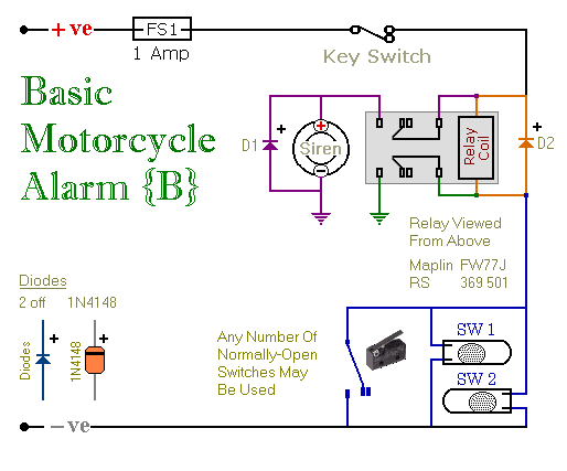
These are two easy-to-build relay-based alarms. They can be used to protect a motorcycle, but they have many additional applications. When using relays with 6-volt coils, they can safeguard a classic bike. Both alarms are compact, with completed boards...

A monostable multivibrator (MMV) features one stable state and one quasi-stable state. The circuit remains in its stable state until an external triggering pulse prompts a transition to the quasi-stable state. After a designated time period T, the circuit...

The construction LED circuit illustrated in the figure requires manual power. Once powered, the light will blink to alert individuals to pay attention to safety. The circuit is designed to enhance safety awareness in construction environments by utilizing a blinking...
The circuit integrates several functions, including a smooth startup for the AC power line, with a one-second delay before connecting to the power supply transformers of the amplifier through relay RL1 and resistor Rx. This delay is designed to...
Warning: include(partials/cookie-banner.php): Failed to open stream: Permission denied in /var/www/html/nextgr/view-circuit.php on line 713
Warning: include(): Failed opening 'partials/cookie-banner.php' for inclusion (include_path='.:/usr/share/php') in /var/www/html/nextgr/view-circuit.php on line 713