
Two Relay-Based Motorcycle Alarm Circuits
The described relay-based alarm circuits are designed for versatility and compactness, making them suitable for a variety of applications beyond motorcycle security. The use of relays allows for the integration of multiple triggering mechanisms, such as mercury and micro-switches, enabling users to customize the alarm's response to various conditions. The choice of relay type, whether SPST, SPDT, DPST, or DPDT, offers flexibility in design while maintaining functionality.
The inclusion of diodes D1 and D2 is critical for safeguarding any connected electronic components from voltage spikes that may occur during relay operation. This precaution is especially important in installations where sensitive devices share the same power supply. The configuration options provided through the inclusion of SPST switches or solder bridges allow users to tailor the alarm's behavior based on their specific needs, whether they are present or away from the motorcycle.
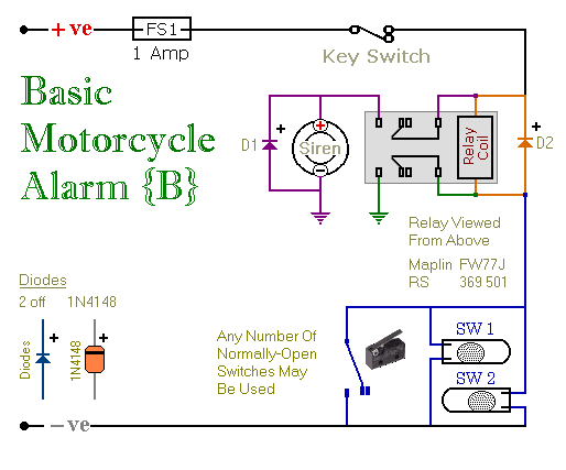
Overall, these relay-based alarm systems are a practical solution for enhancing security in various settings, providing reliable operation with minimal power consumption. The compact design and ease of assembly make them accessible for hobbyists and professionals alike, ensuring that users can implement effective security measures without significant investment in space or resources.These are two - easy to build - relay-based alarms. You can use them to protect your motorcycle - but they have many more applications. If you use relays with 6-volt coils - they`ll protect your "Classic Bike". Both alarms are very small. The completed boards occupy about half a cubic-inch - 8 cc. The standby current is zero - so they won`t drain your battery. Circuit Number Five uses a SPCO/SPDT relay - but you really only need to use a SPST relay. If you are going to use the veroboard layout provided - you`ll need to use the style of relay specified. But you can build the alarm using whatever style of relay you have available. Any number of normally-open switches may be used. Fit the mercury switches so that they close when the steering is moved or when the bike is lifted off its side-stand or pushed forward off its centre-stand.
Use micro-switches to protect removable panels and the lids of panniers etc. When one of the trigger-switches is closed - the relay will energize and the siren will sound. You can choose what happens next. If you build the circuit as shown, the siren will continue to sound until you turn it off - or until the battery is exhausted. But, if you leave out D3 - the siren will stop sounding immediately the trigger-switch is re-opened. While you`re within earshot of your machine - the former configuration is best. You can always turn off the alarm yourself. But if you are going to be away from your bike for any length of time - and you don`t want to cause a nuisance - then the latter configuration is probably more suitable.
If you include a SPST switch in series with D3 - you can select the behaviour that best suits the circumstances at any given time. Relay coils and some sounders produce high reverse-voltage spikes that will destroy sensitive electronic components.
D1 and D2 are there to short-circuit these spikes before they can do any damage. Although there is nothing in the alarm circuit itself that could be damaged - I have no idea what other electronic equipment might be connected to the same power supply. So I included the two diodes as a precaution. If you`re satisfied that there`s nothing on your bike that might be damaged in this way - you can leave out the two diodes.
Circuit Number Six uses a DPCO/DPDT relay - but you really only need to use a DPST relay. If you are going to use the veroboard layout provided - you`ll need to use the style of relay specified. But you can build the alarm using whatever style of relay you have available. Any number of normally-open switches may be used. Fit the mercury switches so that they close when the steering is moved or when the bike is lifted off its side-stand or pushed forward off its centre-stand.
Use micro-switches to protect removable panels and the lids of panniers etc. When one of the trigger-switches is closed - the relay will energize and the siren will sound. You can choose what happens next. If you build the circuit as shown, the siren will continue to sound until you turn it off - or until the battery is exhausted. But, if you leave out the (yellow) solder-bridge in the top left-hand corner - the siren will stop sounding immediately the trigger-switch is re-opened.
While you`re within earshot of your machine - the former configuration is best. You can always turn off the alarm yourself. But if you are going to be away from your bike for any length of time - and you don`t want to cause a nuisance - then the latter configuration is probably more suitable. Connect a SPST switch in place of the (yellow) solder-bridge - and you can select the behaviour that best suits the circumstances at any given time.
Relay coils and some sounders produce high reverse-voltage spikes that will destroy sensitive electronic components. D1 and D2 are there to short-circuit these spikes before they can do any damage. Although there is nothing in the alarm circuit itself that could be damaged - I have no 🔗 External reference
Related Circuits
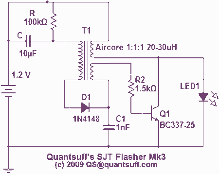
The parts to the right of T1 form a simple Joule-thief ('Blocking' oscillator) circuit which boosts the 1.2v supply to 3.5v to operate the LED. C1 is used to extend the charge and discharge cycles to increase brightness and...

A new type of infrared system utilizes the TX05C radio sensor module for a burglar alarm designed for doors and windows. This system operates in the infrared spectrum, which is invisible to the human eye, making it suitable for...
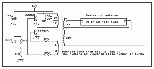
Here is the schematic diagram for a 20 Watt driver. I developed this circuit in 1985, and used it to build a lamp that found much use both as camping light and as emergency light during the then-frequent power...

This circuit requires the bridging of two circuits to activate the electronic switch. It does not require a 60-Hz field to operate and can be powered by either battery or AC. The two pickup terminals can be made from...

The SOS Alarm centralized control circuit is designed for use in calling a hospital bed and can also serve as an anti-theft alarm in multi-storey buildings, dormitories, warehouses, and similar locations. The circuit, as depicted in Figure 13-64, features...
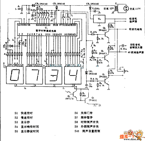
U1 is the 3817 integrated circuit, capable of directly driving the display. It can show time in either 12-hour or 24-hour format, schedule alarm sounds, and automatically turn on the radio at specified times. The display utilizes the FND500...