
One-way operation of a dynamic braking circuit

The 3133 circuit design incorporates a dynamic braking system that is essential for applications where rapid deceleration of motors is required. The circuit operates by converting the kinetic energy of the motor into electrical energy, which is then dissipated as heat in a resistive load.
The dynamic braking system is controlled manually through a set of buttons, allowing operators to engage or disengage the braking process as needed. This feature is particularly useful in scenarios where immediate stopping is necessary, such as in conveyor systems or industrial machinery.
The power supply for the dynamic braking circuit is derived from a step-down transformer, which reduces the AC voltage to a level suitable for the rectification process. The rectifier bridge converts the AC voltage to DC, providing a stable power source for the braking system. The inclusion of diodes in the circuit ensures that current flows in the correct direction, allowing for effective energy conversion during the braking phase.
Furthermore, the circuit's design is optimized for motors rated up to 7.5 kW, making it a reliable choice for medium-sized applications. For larger motors, it is advisable to implement a three-phase rectifier circuit to handle the increased power demands efficiently. This adaptation ensures that the braking system remains effective and responsive, even under high-load conditions.
Overall, the 3133 circuit exemplifies a practical approach to dynamic braking in electric motor applications, combining manual control with robust electrical components to achieve effective deceleration and energy management.3133 circuit shown in FIG. Figure 3-133 (a), dynamic braking (b), (c) the three lines by manually (button) control. Wherein FIG. (A), (b) the dynamic braking DC power supply wi th step-down transformer, rectifier bridge rectifier obtained, FIG. (C) The current power dynamic braking win by a diode obtained similar they work, but the former than the latter braking effect is good. This circuit, commonly used in the following 7. 5kW, braking demanding situations. For larger power motors, brake should be used with DC power three-phase rectifier circuit.
Related Circuits
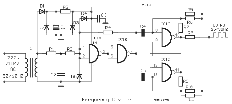
This is a classic frequency divider by two, implemented using a T-flip flop circuit, specifically with IC1 [4011]. In this circuit, the frequency from the network, after limiting the negative half-period of the sine wave and transforming it into...
A newcomer to electronics has questions regarding the interpretation of circuit diagrams. There is uncertainty about the arrangement of wires in these diagrams. Understanding circuit diagrams is essential for anyone involved in electronics, as they serve as a visual representation...
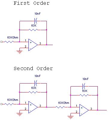
The circuit design involves a circular operational amplifier (op-amp) configuration that functions as a second-order low-pass and high-pass filter. The low-pass filter operates within a frequency range of 20 to 250 Hz, while details regarding the high-pass filter are...
This simple circuit tests speakers, microphones, transformers, and voltage. It is essentially a very low-frequency oscillator that generates extremely short, distinctive pulses. The sound produced is easy to hear and allows for precise localization, making it ideal for checking...
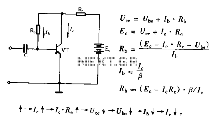
Bias voltage negative feedback circuit The bias voltage negative feedback circuit is a crucial component in various electronic applications, particularly in amplifiers and oscillators. This circuit is designed to stabilize the operating point of a transistor or operational amplifier by...
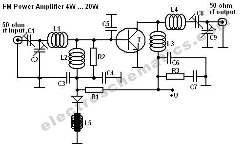
This FM RF power amplifier circuit is constructed using a BLY94 transistor, which can deliver up to 50W at a frequency of 175MHz with a power gain of 7dB, resulting in approximately 5 times power amplification. However, in this...