
Audio Circuit(BassMidTreble)
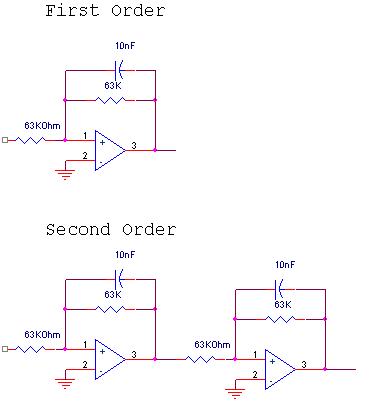
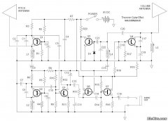
The described circuit utilizes an operational amplifier in a circular configuration, which is typically employed to achieve a second-order filtering effect. In this design, the low-pass filter is designed to allow signals within the frequency range of 20 to 250 Hz to pass through while attenuating frequencies above this range. This characteristic is crucial for applications such as audio processing, where it is important to eliminate unwanted high-frequency noise while preserving the integrity of lower-frequency signals.
The high-pass filter aspect of the circuit, while not elaborated upon, would serve to block signals below a certain cutoff frequency, allowing higher frequencies to pass. The design of such a filter typically involves selecting appropriate resistor and capacitor values to establish the desired cutoff frequency, which is essential for tailoring the circuit's response to specific application requirements.
In a comprehensive schematic, the op-amp would be configured with feedback and input resistors, along with capacitors that define the cutoff frequencies for both the low-pass and high-pass filters. The design may also include considerations for power supply decoupling to enhance performance and stability.
Overall, the circular op-amp configuration is a versatile approach that can be adapted for various filtering applications, making it a valuable design for engineers seeking effective solutions in signal processing.I don`t know if this is a good design or not.Circle Op-amp are 2nd order low/high pass filter. Low pass filter range is 20-250Hz High pass filter.. 🔗 External reference
Related Circuits
Assembly is straightforward; simply follow the PCB overlay. Ensure that the integrated circuit and the electrolytic capacitors are oriented correctly. The electrolytic capacitors are polarized, marked with a + or - sign, and must be installed properly into the...
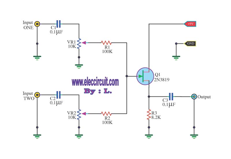
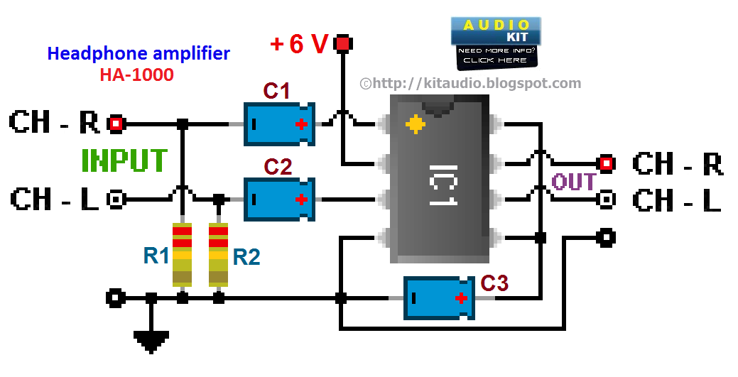
This circuit is a simple mixer circuit that can mix two signal channels into one output channel. It utilizes a codec circuit to convert stereo audio into mono audio. The circuit can also increase the number of channels by...
A compact power amplifier that delivers high-quality sound. It incorporates a NE5534 operational amplifier, known for its excellent performance, capable of handling low loads, providing high speed, and exhibiting low distortion. Additionally, it features two V-MOSFET transistors at the...
The PT2399 digital echo circuit schematic is an electronic design that utilizes the PT2399 integrated circuit (IC) for audio applications. This digital echo processor, based on CMOS technology, incorporates both analog-to-digital conversion (ADC) and digital-to-analog conversion (DAC) processes for...
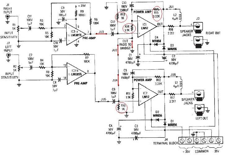
The LM12 audio amplifier circuit is designed to deliver high output power for 8 ohm or 4 ohm load impedances. The maximum output power provided by the LM12 audio amplifier is approximately 60 watts for a 4 ohm load...
The three stages commonly found in audio amplifiers and operational amplifiers are clearly visible. However, actual audio designs often feature modifications and enhancements in key areas. This overview highlights design improvements in audio amplifiers, focusing on each of the...
Warning: include(partials/cookie-banner.php): Failed to open stream: Permission denied in /var/www/html/nextgr/view-circuit.php on line 713
Warning: include(): Failed opening 'partials/cookie-banner.php' for inclusion (include_path='.:/usr/share/php') in /var/www/html/nextgr/view-circuit.php on line 713