
optimized 6 element uhf yagi antenna
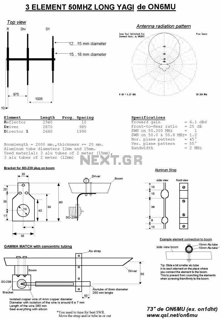
The antenna design described involves a configuration where the elements are strategically arranged to optimize performance while maintaining flexibility in component sizing. The choice of element diameters, specifically the 5.8 mm for the antenna elements and the recommended 12 mm for the dipole, allows for a balance between structural integrity and electrical characteristics.
The boom serves as a central support structure, providing mechanical stability and facilitating the electrical connection of the elements. This configuration ensures that all elements, except the dipole, are grounded to the boom, which minimizes interference and enhances signal quality. The mounting options—either on top of or through the boom—offer versatility in installation, allowing for customization based on specific application requirements or environmental conditions.
In practice, this antenna design can be utilized in various applications, including amateur radio, television reception, and other communication systems. The ability to maintain the same length and spacing while varying the diameters of the elements simplifies the tuning process and reduces the need for extensive recalibration. This feature is particularly advantageous in field applications where quick adjustments are necessary.
Overall, the described antenna configuration presents a robust solution for achieving effective communication while allowing for adaptability in its physical design. The careful consideration of element size and mounting techniques contributes to the overall efficacy of the antenna system.The elements diameter of the antenna may vary between 5. 8mm and the dipole diameter may vary between 8. 12mm (12mm recommended) without the need of changing anything to the length or spacing. All elements except the dipole are electrically connected to the boom and may be mounted on top or through it. 🔗 External reference
Related Circuits
This AM/FM antenna booster circuit amplifies the broadband signal from the antenna. This antenna booster is designed to work for FM, AM, and SW receivers. The AM/FM antenna booster circuit is an essential component for enhancing radio reception across...
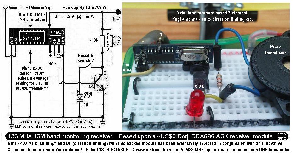
This is a simple 433.92 MHz short-range radio beacon that can be useful for locating downed R/C planes, lost balloons, model rockets, or possibly hidden items. The 433.92 MHz short-range radio beacon circuit is designed to transmit a signal over...
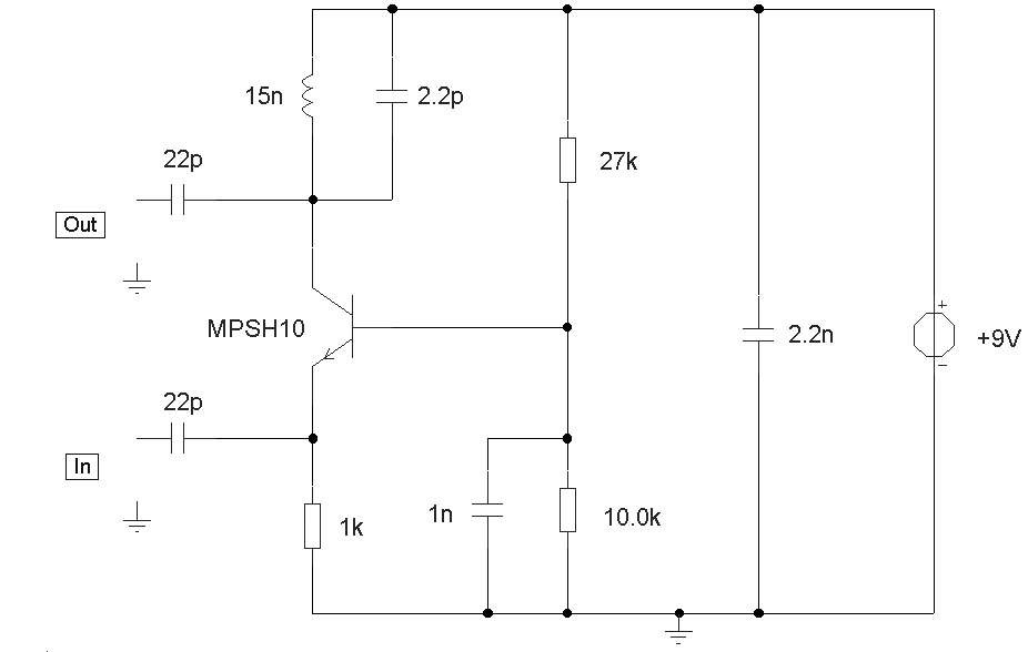
This circuit is designed to work at UHF frequencies in the range 450-800MHz. It has a gain of around 10dB and is suitable for boosting weak TV signals. The circuit is shown below. The described circuit operates within the Ultra...
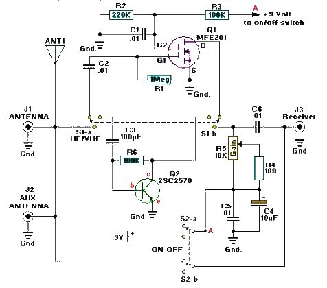
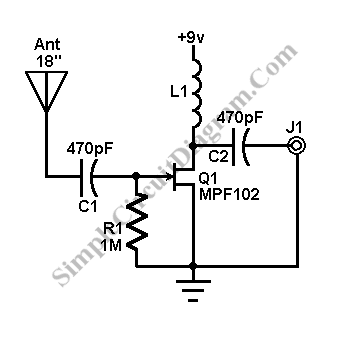
A simple and efficient active antenna electronic project can be designed using this electronic schematic circuit based on transistors. This active antenna project is effective for a wide range of RF frequencies, covering three RF bands: HF, VHF, and...
This antenna signal booster is designed for TV receivers operating in the UHF band (400-850 MHz) and provides an amplification of approximately 10 to 15 dB. The schematic diagram of the circuit indicates that special attention is necessary for...
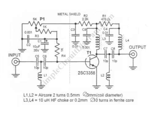
The circuit design aims to create a preamplifier for television systems that operates within the UHF frequency range of 450 MHz to 800 MHz. The preamplifier circuit is essential for enhancing weak television signals before they are processed by the...