
VHF UHF HF active antenna electronic circuit project with explanation
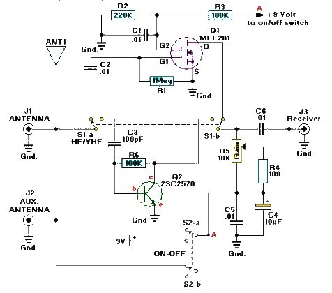
The active antenna circuit described is designed to enhance signal reception across various radio frequency bands, making it versatile for different applications. The MFE201 dual-gate MOSFET serves as a key component in achieving high gain and low noise performance, which is essential for effective RF amplification. The use of the 2SC2570 NPN transistor complements the MOSFET by providing additional amplification for the VHF range, ensuring that weak signals can be boosted for better clarity and reception.
The implementation of dual DPDT switches allows for user-friendly operation, enabling the selection between the HF and VHF/UHF pre-amplifiers depending on the user's needs. This feature is particularly advantageous for users who may want to switch bands without the need for additional circuitry or manual adjustments. Furthermore, the ability to bypass the amplification stage by turning off the circuit through switch S2 allows for direct RF signal coupling, which can be beneficial in scenarios where amplification is not required or when testing the receiver's performance with a direct signal.
Powering the circuit with a 9-volt DC supply ensures that it remains compact and portable, making it suitable for indoor use where space may be limited. The design's simplicity not only makes it accessible for hobbyists and electronics enthusiasts but also allows for easy troubleshooting and modifications. Overall, this active antenna project exemplifies an effective solution for enhancing RF signal reception across multiple frequency bands while maintaining ease of use and practicality.A very simple and efficiency active antenna electronic project can be designed using this electronic schematic circuit that is based on transistors. This active antenna electronic project is useful for a wide range of RF frequencies covering three RF bands HF, VHF and UHF.
This simple active antenna is designed to amplify signals from 3 to 3000 MegaHertz, including three recognized ranges: 3-30Mhz high-frequency (HF) signals; 3-300Mhz veryhigh frequency (VHF) signals; 300-3000MHz ultra-high (UHF) frequency signals. MFE201 N-Channel dual-gate MOSFET) and Q2 (which is an 2SC2570 NPN VHF silicon transistor). Those transistors provide the basis of two independent, switchable RF pre-amplifiers. Two DPDT switches play a major role in this circuit, switch S1 used to select one of the two pre-amplifier circuits (either HF or VHF/UHF) and switch 2 is used to turn off the power to the circuit, while coupling the incoming RF directly to the input of the receiver.
This circuit must be powered from a simple 9 volt DC power circuit ( or a 9 volts battery) and is very useful for use as an indoor antenna 🔗 External reference
Related Circuits
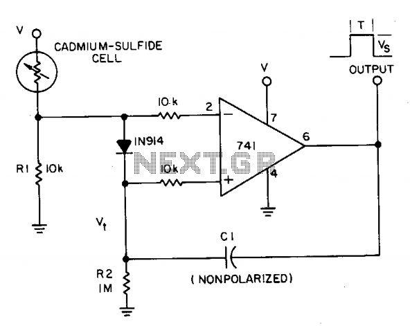
A photocell circuit provides automatic threshold adjustment. Monostable action prevents undesired retriggering of the output. With only one op amp IC, the circuit offers automatic adjustment of its trigger level to accommodate various light sources, changes in ambient light,...
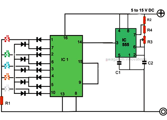
An LED light chaser circuit is an electronic configuration designed to illuminate a group of LEDs in a predetermined sequence. A commonly used integrated circuit (IC) for creating this type of LED sequencer circuit is the 4017. This IC...
This device is a simple timer that keeps the headlights of a vehicle on for approximately 1 minute and 30 seconds, allowing for illumination when accessing dark areas without the need to return to switch off the lights. Pressing...
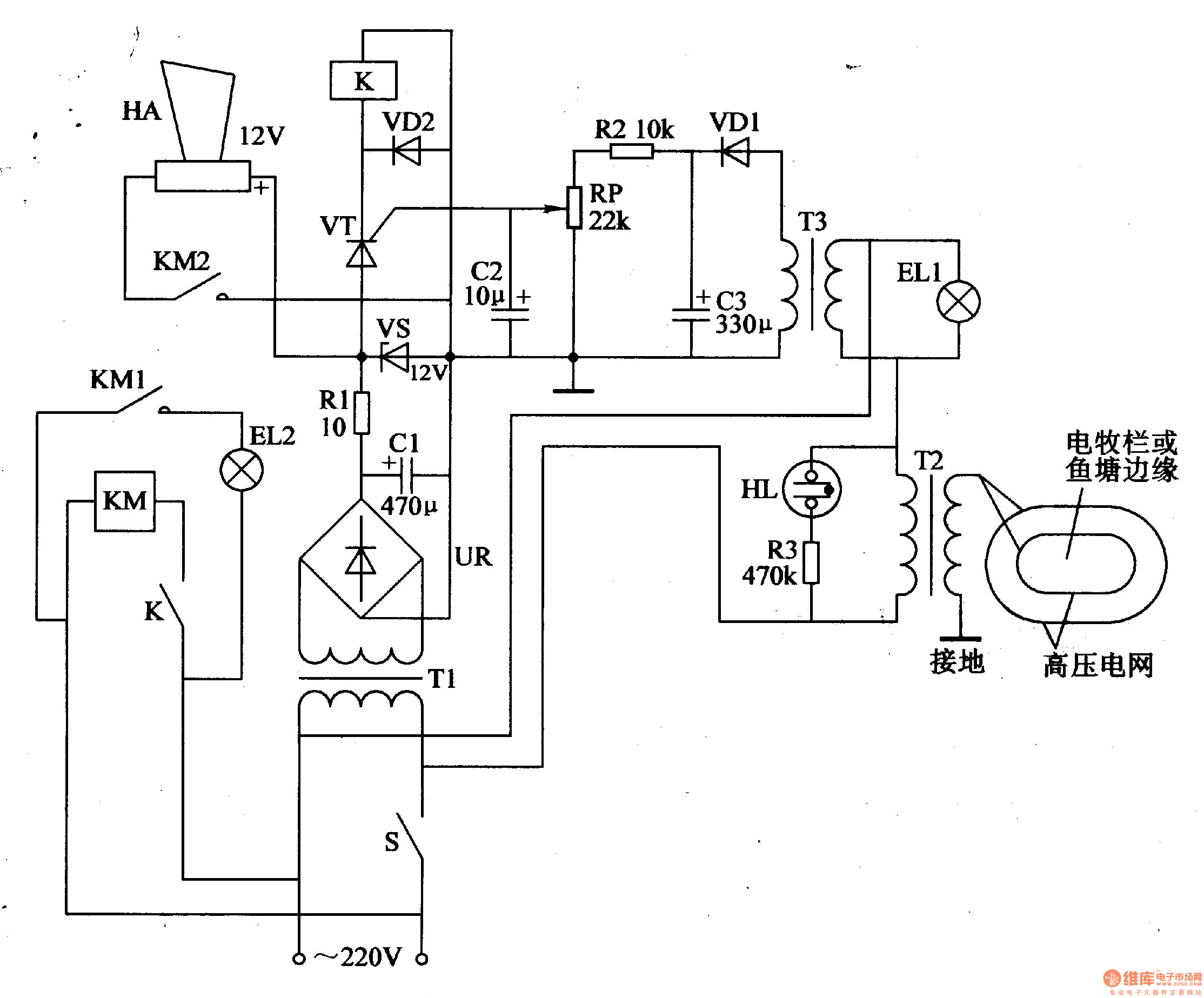
The electric fence control circuit consists of three main components: the power supply circuit, the high voltage circuit, and the sound and light alarm circuit, as illustrated in Figure 4-26. The power supply circuit includes a power switch (S),...
High Power Siren Circuit. This article discusses a robust siren circuit suitable for various applications. A complementary transistor pair (BC557 & BC337) is configured as an oscillator to directly drive the speaker. Transistor Q1 (BC557) is utilized to ensure...
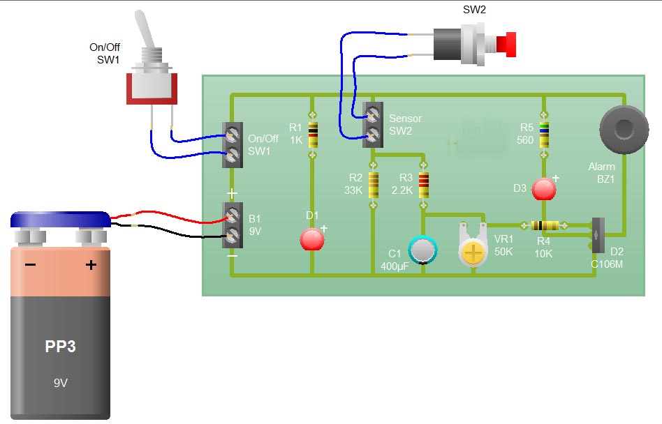
When the sensor switch SW2 is pressed, the LED D3 and the alarm are activated for a certain duration. The timing of the circuit is determined by the resistor R3 and capacitor C1. Additional details regarding the RC circuit...
Warning: include(partials/cookie-banner.php): Failed to open stream: Permission denied in /var/www/html/nextgr/view-circuit.php on line 713
Warning: include(): Failed opening 'partials/cookie-banner.php' for inclusion (include_path='.:/usr/share/php') in /var/www/html/nextgr/view-circuit.php on line 713