
oscillator

An oscillator serves as a fundamental component in various electronic applications, providing essential timing signals for circuits. In the context of a phase shift oscillator, the arrangement of three RC filters is critical in establishing the necessary phase shift for sustained oscillation. The inverting amplifier plays a pivotal role by providing the required gain and ensuring that the feedback loop maintains the oscillation condition defined by the Barkhausen criterion, which states that the total loop gain must equal unity at the desired frequency, with a total phase shift of 360 degrees.
The Hartley oscillator is particularly notable for its simplicity and effectiveness in generating radio frequency signals. Its design allows for easy tuning by adjusting the inductance or capacitance within the tank circuit, facilitating applications in RF transmission and reception. The feedback mechanism through the tapped coil enables a stable oscillation that can be finely adjusted, making it suitable for various communication systems.
The Clapp oscillator, on the other hand, is recognized for its superior frequency stability and ease of tuning. Its design minimizes the effects of parasitic capacitance and inductance, which can adversely affect oscillation frequency. By incorporating fixed capacitors in the voltage divider, the Clapp oscillator achieves a more reliable feedback mechanism, essential for applications requiring precise frequency control, such as in signal generators and synthesizers.
In summary, oscillators are vital in electronic systems, with various designs like the phase shift, Hartley, and Clapp oscillators catering to specific needs in frequency generation and stability. Understanding their operational principles and configurations is essential for engineers designing circuits that rely on accurate timing and frequency signals.An oscillator is a circuit that can generate a frequency source such as a sine wave, square wave or pulse train. An oscillator is fundamentally a combination of a frequency-sensitive circuit such as an LC circuit or a crystal and a negative resistance usually obtained by using an amplifier with positive feedback.
Phase shift is the displacement of a waveform in time. For example, if a waveform is displaced by a complete wavelength. it is described as having a phase-shift of 360 °. If it is displaced by half a wavelength (i. e. 180 °) one wave will peak where the other is in a trough state and complete cancellation will result. If they are at any other angle of phase-shift, partial cancellation will result. A phase shift oscillator is a simple sine wave electronic oscillator. It contains an inverting amplifier, and a feedback filter which `shifts` the phase by 180 degrees at the oscillation frequency.
The most common way of achieving this kind of filter is using 3 cascaded resistor-capacitor filters, at the oscillation frequency each filter produces a phase shift of 60 degrees and the whole filter circuit produces a phase shift of 180 degrees. Thus the total phase shift produced by the three RC networks is 180 °. Therefore at the specific frequency fo the total phase shift from the base of the transistor around the circuit and back to the base is 360 ° The mathematics for calculating the oscillation frequency and oscillation criteria for this circuit are surprisingly complex, due to each R-C stage loading the previous ones.
The calculations are greatly simplified by setting all the resistors (except the -ve feedback resistor) and all the capacitors to the same values. In the diagram, if R1 = R2 = R3 = R, and C1 = C2 = C3 = C, then: The Hartley oscillator was invented by Ralph.
V. L. Hartley while he was working for the Research Laboratory of the Western Electric Company. Hartley invented the design while overseeing Bell System`s transatlantic radiotelephone tests of 1915. who filed for a patent on June 1, 1915 and was awarded patent number 1, 356, 763 on October 26, 1920.
The Hartley oscillator is an LC electronic oscillator that derives its feedback from a tapped coil in parallel with a capacitor (the tank circuit). Although there is no requirement for there to be mutual coupling between the two coil segments, the circuit is usually implemented as such.
A Hartley oscillator is essentially any configuration that uses a pair of series-connected coils and a single capacitor. The Clapp oscillator is one of several types of electronic oscillator constructed from a transistor (or vacuum tube) and a positive feedback network.
It was invented by James K. Clapp in 1948. The network is comprised of a single inductor and three capacitors, with two capacitors (C1 and C2) forming a voltage divider that determines the amount of feedback voltage applied to the transistor input. The Clapp oscillator is a Colpitts oscillator with an additional capacitor placed in series with the inductor.
The oscillation frequency in hertz (cycles per second) for the circuit in the figure, which uses a field-effect transistor (FET), is A Clapp circuit is often preferred over a Colpitts circuit for constructing a variable frequency oscillator (VFO). In a Colpitts VFO, the voltage divider contains the variable capacitor (either C1 or C2). This causes the feedback voltage to be variable as well, sometimes making the Colpitts circuit less likely to achieve oscillation over a portion of the desired frequency range.
This problem is avoided in the Clapp circuit by using fixed capacitors in the voltage divider and a variable capacitor (C0) in series with the inductor. 🔗 External reference
Related Circuits
Understanding how quartz-crystal resonators operate can lead to designing crystal oscillators with improved stability and better noise performance. Quartz-crystal resonators function based on the piezoelectric effect, where mechanical stress applied to a quartz crystal generates an electrical charge. This property...
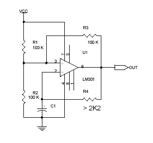
This circuit utilizes the Op-Amp LM301 to generate a simple square wave. The LM301 operates with a power supply range of 3 V to 36 V and can handle a maximum frequency of 325 kHz. The oscillation frequency is...
The figure illustrates a multiple output crystal oscillator, which primarily consists of three gates of Al, four resistors, two capacitors, and a crystal. Resistors R1 to R4 offset two inverters within the linear range and are connected between pin...
A voltage-controlled oscillator (VCO) is an electronic oscillator designed to control its oscillation frequency through a voltage input. The oscillation frequency is varied by the applied DC voltage, and modulating signals can also be introduced to the VCO for...
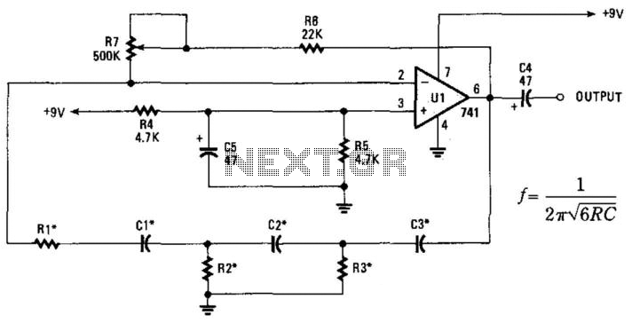
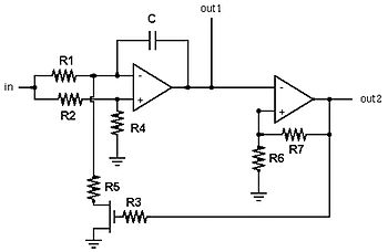
This phase-shift oscillator is suitable for audio oscillator applications. Adjust R7 to achieve a good sine wave. An amplifier gain of 29 is necessary for oscillation. If C=C1=C2=C3 and R=R1=R2=R3: Typically, R will range from 1 to 100 kOhm...
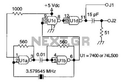
A circuit utilizing one 7400 TTL can operate with fundamental type crystals ranging from 1 to approximately 13 MHz. The output is rich in harmonics, making this oscillator suitable for calibration and testing applications. The circuit in question employs a...