
Square Wave Oscillator
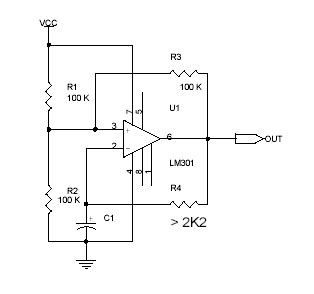
The circuit employs the LM301 operational amplifier in a configuration designed to produce a square wave output. The operational amplifier's power supply range of 3 V to 36 V provides flexibility for various applications. The maximum operating frequency of 325 kHz makes this design suitable for high-speed switching applications.
The oscillation frequency can be calculated using the formula that incorporates the resistances (R) and capacitance (C) in the circuit, allowing for precise tuning of the output waveform. Capacitor C1 plays a critical role in the timing of the oscillation; it must be adequately rated to handle voltages exceeding two-thirds of the supply voltage to ensure reliable operation.
In this configuration, the inverting input of the LM301 is grounded, maintaining it at zero volts. The non-inverting input is biased to approximately two-thirds of the supply voltage through a voltage divider formed by resistors R1, R2, and R3. This setup establishes a threshold voltage that is essential for the operation of the square wave generator.
As the output of the LM301 transitions, C1 charges and discharges, affecting the voltage at the non-inverting input. When the output voltage exceeds the non-inverting input voltage, the output swings down to zero volts, causing a periodic oscillation that produces the square wave output. The timing and frequency of this oscillation can be adjusted by varying the values of R1, R2, R3, and C1, allowing for a versatile design that can be tailored to specific requirements.
In summary, this circuit design effectively utilizes the LM301 operational amplifier to generate a square wave signal, with careful consideration given to component values and configuration to achieve stable and reliable performance.This scheme applies amplifier OpAmp LM301 to awaken square wave that is simple. LM301 applies power allowance 3 V - 36 V, with highest frequency 325 kHzs. Oscillation frequency given in equation. where f is Hertz, R in Ohm, C in Farad. Active Pressure C1 have to be more a few 2/3 of power allowance tensions. At C1 stands to throw away charge. Input inverting IC LM301 becomes zero volts whereas input non-inverting arrested at tension around 2/3 quantized tensions by R1, R2 and R3. C1 now loaded from output of LM301 through finite R4 of the tension exceeding tension at input non-inverting, that is when output of LM301 sways going down to zero volts.
Input non-inverting LM301 has tension around 1/3 allowance tensions. 🔗 External reference
Related Circuits
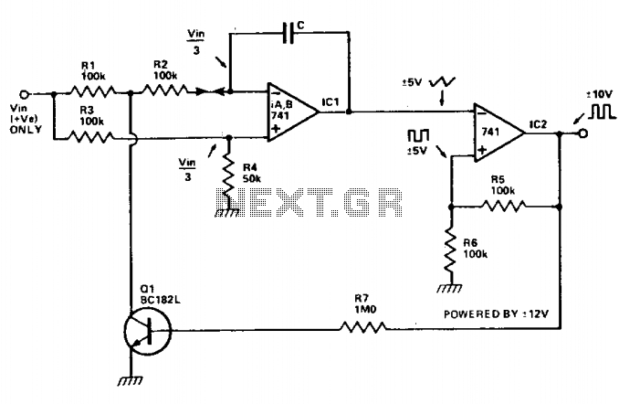
The voltage-controlled oscillator (VCO) features two buffered outputs: a triangle wave and a square wave. The frequency is influenced by the output voltage swing of the Schmitt trigger, IC2. Enhanced performance can be achieved by substituting Q1 with a...
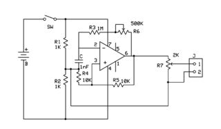
An attempt has been made to follow an instructable for some time; however, understanding its schematic remains challenging. The issue is not a lack of knowledge regarding the symbols used. In electronic schematics, symbols represent various components and their connections...

This is a 100 MHz Varicap Oscillator circuit. This circuit can provide modulation signals of less than 28 V and a frequency deviation of 28 MHz peak-to-peak. The 100 MHz Varicap Oscillator circuit is designed to generate high-frequency signals suitable...
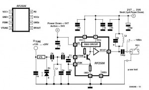
Nowadays, it is no longer necessary to use discrete components to build oscillators. Instead, many manufacturers provide ready-made voltage-controlled oscillators. Modern electronic design has evolved significantly, eliminating the need for discrete components in the construction of oscillators. Voltage-controlled oscillators (VCOs)...
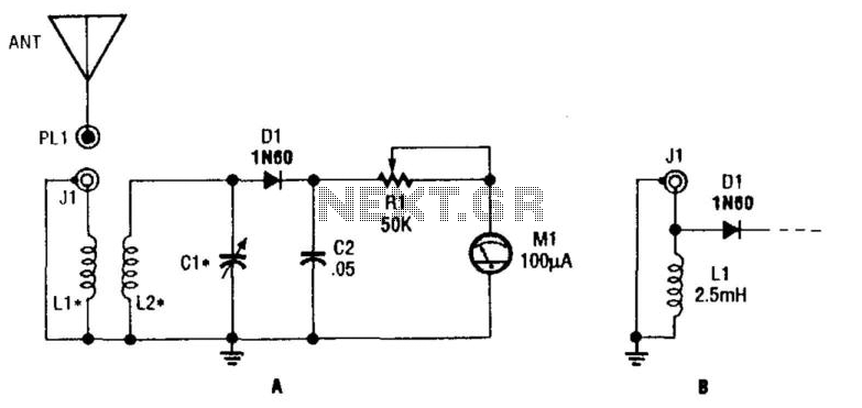
L1 and L2 form a tuned transformer with an optimum turns ratio of approximately 1:3. L2 and C1 are used to tune to the desired frequency. The frequency range can extend from 10 kHz to over 200 MHz, depending...
The circuit was designed to create an electronic oscillator known as a Wien Bridge Oscillator, which can be used for the creation of low-frequency sine waves. The Wien Bridge Oscillator is a type of electronic oscillator that generates sine waves....