
Oscillator Simulation Example Using RINCON
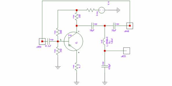
The one-transistor oscillator described operates based on the principles of resonance within an LC circuit, which is characterized by its ability to oscillate at specific frequencies determined by the inductance (L) and capacitance (C) values. The phase-inverting configuration allows for the necessary feedback to sustain oscillations. The Rincon simulator facilitates the simulation of this oscillator by allowing the user to define component models accurately, which are critical for achieving realistic simulation results.
In the frequency sweep analysis, the simulator systematically varies the frequency of the input signal to identify the range over which oscillation can be sustained. This process helps to pinpoint the resonant frequency of the circuit, where the inductive and capacitive reactances are equal, leading to maximum voltage oscillations. Following this, the time domain simulation using the MHB solver provides insight into the transient behavior of the oscillator, illustrating how it responds to initial conditions and external perturbations.
The inclusion of a small amplitude for the input voltage source is crucial for ensuring that the simulation remains within the linear operating region of the transistor, allowing for accurate modeling of the oscillatory behavior without introducing significant distortion. The large-signal simulation approach compensates for the lack of small-signal AC simulation capabilities in Rincon, ensuring that the nonlinear characteristics of the transistor are adequately captured.
The report also emphasizes the versatility of the Rincon simulator, detailing how it can be operated in different modes such as HB and MHB. The HB mode is useful for steady-state analysis of periodic signals, while MHB is advantageous for analyzing modulated signals, providing a comprehensive toolkit for engineers to explore the dynamic behavior of oscillators and similar circuits. This capability is essential for the design and optimization of modern electronic systems where oscillators play a pivotal role in signal generation and processing.To demonstrate Rincon`s capability to simulate autonomous circuits, let us consider one-transistor oscillator, which uses phase-inverting resonance T-shape LC circuit. Schematic of this simulator is shown at fig. 1. Design of simulator is described in details in [2]. For purpose of simulation, let us pay attention to component models first. Then proposed circuit will be simulated in frequency sweep to look does oscillation condition are possible. After that time domain (using MHB solver) simulation will be performed. That code contains f in generic interface of entity. That means that frequency value may be passed there from outside. This frequency is used by vin voltage source. Amplitude of that source is set to 0. 001 to be sure that signal is really small. Rincon does not contain small signal AC simulation, so large-signal simulation is used to compute quantities. This report shows how to use Rincon VHDL-AMS/FD simulator to simulate oscillators in time domain - how to simulate open loop cascade, set up initial condition to start oscillator simulations.
Shown how to run simulator in different modes HB and MHB (Harmonic Balance and Modulated Harmonic Balance). 🔗 External reference
Related Circuits
The CAMD CM8870 CM8870C offers complete DTMF receiver functionality by combining both the band-split filter and digital decoder capabilities into a single 18-pin DIP, SOIC, or 20-pin PLCC package. The CM8870C is produced using advanced CMOS process technology, ensuring...
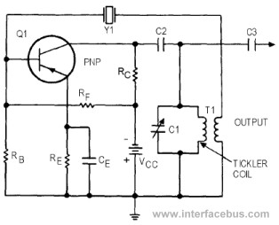
This circuit represents a variant of an Armstrong Oscillator. This specific example incorporates a crystal along with the LC tank circuit utilized in the previous Series-Fed Armstrong Oscillator. By definition, the Armstrong Oscillator employs a tickler coil for feedback...
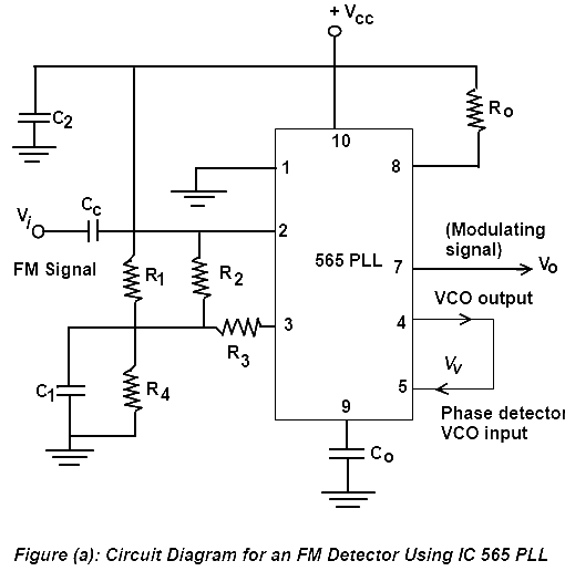
Phase Lock Loop (PLL) FM Detector with 565 PLL IC. The circuit diagram and internal structure of the PLL IC 565 are shown in the given figures. The Phase Lock Loop (PLL) FM Detector utilizing the 565 PLL IC is...
A meter is a measuring instrument. An ammeter measures current, a voltmeter measures the potential difference (voltage) between two points, and an ohmmeter measures resistance. A multimeter combines these functions, and possibly some additional ones, into a single instrument....
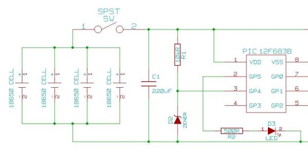
Heavy-duty portable charger for USB devices (phones, iPad, etc.). Have you ever needed to charge your phone on the go? Unable to find a wall socket to charge your iPod?.. The heavy-duty portable charger is designed to provide a reliable...
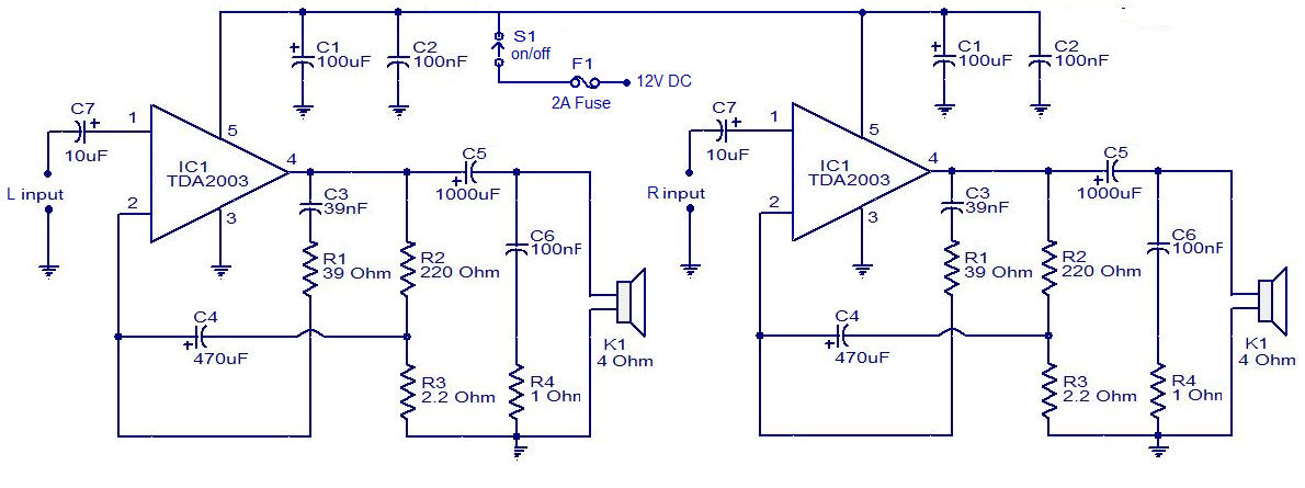
The circuit is easy to construct. The TDA2003 is an integrated radio amplifier from ST Microelectronics that features short circuit protection for all pins, thermal protection, low harmonic distortion, and low crossover distortion. In the circuit provided, the TDA2003...