
using a multimeter
The operation of measuring instruments such as ammeters, voltmeters, and ohmmeters is fundamental in electronic circuit analysis and troubleshooting. An ammeter must be integrated into a circuit in series, which necessitates a break in the circuit to ensure that all current flows through it. This requirement emphasizes the need for an ammeter to exhibit low internal resistance to minimize its impact on the overall circuit behavior. The connection of a voltmeter in parallel, on the other hand, allows it to measure voltage without altering the current flow significantly. This is achieved through its high resistance, which ensures that minimal current is drawn from the circuit, preserving the integrity of the measurement.
When using an ohmmeter, it is crucial to disconnect the component from any power source to prevent potential damage to the meter. The operation of an ohmmeter involves applying a small test current through the component and measuring the resultant voltage, which is then used to calculate the resistance according to Ohm's Law. This separation from the circuit is necessary to obtain accurate resistance values.
Multimeters, which combine the functionalities of these three instruments, are essential tools for electronics engineers. They provide versatility and convenience, allowing for the measurement of current, voltage, and resistance in one device. Digital multimeters offer clear numerical outputs on a liquid crystal display, enhancing usability and reducing the likelihood of misinterpretation compared to analogue counterparts. The user interface, typically featuring a central rotary switch, allows the operator to select the desired measurement type and range, facilitating straightforward operation.
In summary, understanding the correct application and connection of these meters is vital for effective circuit analysis and diagnostics. The design and features of multimeters cater to both novice and experienced users, making them indispensable tools in the field of electronics.A meter is a measuring instrument. An ammeter measures current, a voltmeter measures the potential difference (voltage) between two points, and an ohmmeter measures resistance. A multimeter combines these functions, and possibly some additional ones as well, into a single instrument.
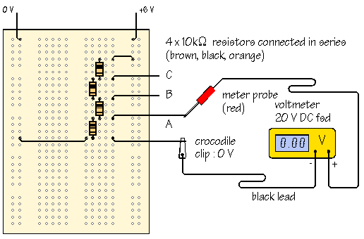
Before going in to detail about multimeters, it is important for you to have a clear idea of how meters are connected into circuits. Diagrams A and B below show a circuit before and after connecting an ammeter: Think about the changes you would have to make to a practical circuit in order to include the ammeter. To start with, you need to break the circuit so that the ammeter can be connected in series. All the current flowing in the circuit must pass through the ammeter. Meters are not supposed to alter the behaviour of the circuit, or at least not significantly, and it follows that an ammeter must have a very LOW resistance.
This time, you do not need to break the circuit. The voltmeter is connected in parallel between the two points where the measurement is to be made. Since the voltmeter provides a parallel pathway, it should take as little current as possible. In other words, a voltmeter should have a very HIGH resistance. The processing of electronic signals is usually thought of in voltage terms. It is an added advantage that a voltage measurement is easier to make. The orginal circuit does not need to be changed. Often, the meter probes are connected simply by touching them to the points of interest. An ohmmeter does not function with a circuit connected to a power supply. If you want to measure the resistance of a particular component, you must take it out of the circuit altogether and test it separately, as shown in diagram D: Ohmmeters work by passing a small current through the component and measuring the voltage produced. If you try this with the component connected into a circuit with a power supply, the most likely result is that the meter will be damaged.
Most multimeters have a fuse to help protect against misuse. Multimeters are designed and mass produced for electronics engineers. Even the simplest and cheapest types may include features which you are not likely to use. Digital meters give an output in numbers, usually on a liquid crystal display. The central knob has lots of positions and you must choose which one is appropriate for the measurement you want to make. If the meter is switched to 20VDC, for example, then 20V is the maximum voltage which can be measured, This is sometimes called 20V fsd, where fsd is short for full scale deflection.
For circuits with power supplies of up to 20V, which includes all the circuits you are likely to build, the 20VDC voltage range is the most useful. DC ranges are indicated by What does DC mean DC means direct current. In any circuit which operates from a steady voltage source, such as a battery, current flow is always in the same direction.
Every constructional project descirbed in Design Electronics works in this way. AC means alternating current. In an electric lamp connected to the domestic mains electricity, current flows first one way, then the other. That is, the current reverses, or alternates, in direction. With UK mains, the current reverses 50 times per second. The central knob has fewer positions and all you need to do is to switch it to the quantity you want to measure.
Once switched to V, the meter automatically adjusts its range to give a meaningful reading, and the display includes the unit of measurement, V or mV. This type of meter is more expensive, but obviously much easier to use. Where are the two meter probes connected The black lead is always connected into the socket marked COM, short for COMMON.
The red lead is connected into the socket labelled V An analogue meter moves a needle along a scale. Switched range analogue multimeters are very cheap but are difficult for beginners to read accurately, esp 🔗 External reference
Related Circuits
The SP1481E, SP1485E, SP1490E, and SP1491E series transceivers, combined with the SP6652 high-efficiency, high-frequency current mode PWM buck regulator, facilitate the creation of an isolated RS-485 interface capable of providing up to 2kVrms isolation. This configuration supports CAN communication...
Binary Amplitude Shift Keying (BASK), also known as On-Off Keying (OOK), is a digital modulation technique where the amplitude of the carrier signal is altered according to binary data. This modulation scheme is utilized for transmitting digital information over...
This post discusses a proximity detector circuit primarily utilizing the NE555 integrated circuit (IC). The circuit is designed for burglar alarms based on beam interruption, with the advantage that the transmitter and receiver are contained within the same enclosure,...

A simple instrumentation amplifier circuit diagram utilizing an operational amplifier (op-amp). The equation for gain, along with design, working principles, and construction details, are also provided. An instrumentation amplifier is a type of differential amplifier that has been designed to...
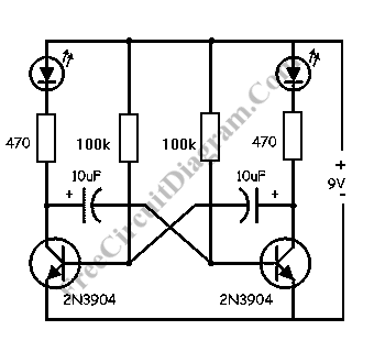
This LED flasher circuit is a classic two-transistor flip-flop. It is a popular circuit often built by beginners in electronic circuit design. The schematic diagram of this well-known LED flasher circuit consists of two transistors, two capacitors, four resistors,...

If you have ever used a 12V flasher relay system, typically a mechanical type, for general automotive applications, today we will attempt to build a 12V flasher relay circuit. The 12V flasher relay circuit is a crucial component in automotive...