
A block diagram of AN6657 and basic application circuit
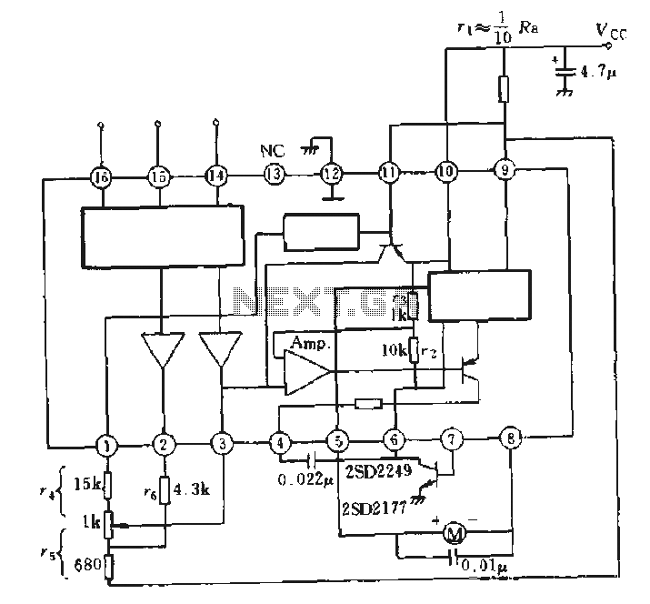
The AN6657 and AN6657S integrated circuits are designed for motor control applications, specifically for driving DC motors with bidirectional capability. The internal H-bridge configuration allows for efficient control of motor direction and speed by utilizing pulse width modulation (PWM) techniques. The device is capable of handling the required current levels to operate small to medium-sized motors, making it suitable for various applications, including robotics, automation systems, and consumer electronics.
In operation, the H-bridge driver outputs on pins 5 and 8 are responsible for controlling the polarity of the voltage applied to the motor terminals. When pin 5 is activated (set to a high logic level), current flows through the motor in one direction, causing it to rotate forward. Conversely, activating pin 8 reverses the polarity, allowing the motor to rotate in the opposite direction. The ability to control motor speed is achieved by modulating the duty cycle of the PWM signal applied to the enable pin, which is typically connected to an external control circuit.
The positive supply voltage for the H-bridge is provided through pins 9 and 11. This supply voltage must be stable and within the specified operating range to ensure reliable motor operation. Additionally, the external electrical contact resistance (R VCC) plays a crucial role in limiting the current and protecting the integrated circuit from overcurrent conditions.
Pin 6 serves as the connection point for the H-bridge arm, while the external NPN transistor connected to this pin is utilized to ground the circuit, enabling or disabling the motor operation based on the control signals. This configuration allows for enhanced control over the motor's behavior, including features such as braking and coasting.
Overall, the AN6657 series provides a compact and efficient solution for motor control applications, integrating essential features into a single package to simplify design and implementation.AN6657 is a 16-pin dual in-line plastic package, AN6657S 16-pin dual flat plastic package. 1. Speed Control works with internal H-bridge driver chip circuit, 5 and 8 feet H-bridge driver output, then charged motor. When 5 feet is positive, the motor is transferred; when 8 feet is positive, reverse the motor. H-bridge positive supply 9 and 11 feet, after an external electrical contact resistance r vcc. H bridge arm connected to 6 feet, after an external NPN transistor is grounded, see solid
Related Circuits
Pressing the pushbutton on the transmitter activates a sound and/or light alert in the receiver. This system operates without wiring or radio frequencies; instead, the transmitted signal is conveyed through the mains supply line. It is suitable for use...
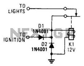
A relay and two diodes are all that is needed; the relay performs the job of a buzzer, so no annunciator is required. When the lights are left on while the ignition is off, the normally closed relay contacts...
A highly effective 1-watt FM transmitter circuit that is easy to construct. The circuit consists of four transistors: one functions as a stable oscillator, followed by a buffer stage to maintain frequency stability during adjustments. Next is a resonance...
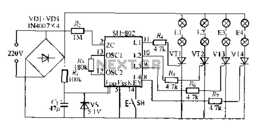
A digital integrated circuit simplifies the response process significantly. The diagram illustrates a circuit comprising four responder groups. The digital integrated circuit described serves as a crucial component in various electronic systems, primarily focusing on enhancing response efficiency. It comprises...
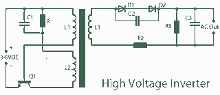
A 3V to 1000V inverter circuit has been constructed, but it is not functioning as intended. The creator seeks expert assistance to identify potential errors in the circuit design. Additionally, there is uncertainty regarding the transformer construction, as the...
AN79 Linear Technology AN79 modifies methods presented in AN74, allowing for the verification of 30 nanosecond amplifier settling times with 0.1% resolution. The sampling-based technique used is detailed, and results are presented. Appendices cover oscilloscope overdrive issues, the construction...