
Mains Remote-Alert circuit
The described system utilizes a power line communication (PLC) technology, which allows for the transmission of signals over existing electrical wiring. This method eliminates the need for additional wiring or complex installations, making it an efficient solution for alert systems in residential settings.
The transmitter is equipped with a pushbutton switch that, when pressed, generates a signal. This signal is then modulated and superimposed onto the mains voltage, allowing it to travel through the electrical infrastructure of the building. The receiver, connected to the same mains supply, detects this modulated signal and responds by activating an alert mechanism, which can be either an auditory sound or a visual light indicator.
To ensure effective communication between the transmitter and receiver, both devices must be powered from the same electrical circuit. This requirement is crucial, as the signal relies on the integrity of the mains supply line for transmission. The performance of the system is influenced by factors such as the quality of the electrical connections, the presence of interference from other devices, and the overall layout of the electrical wiring within the building.
Installation is straightforward; users simply need to plug the transmitter and receiver into available wall sockets. This plug-and-play feature enhances the system's usability, allowing for quick deployment in various environments. The range of the system can vary based on the electrical setup, but it generally provides reliable operation throughout a typical residential structure.
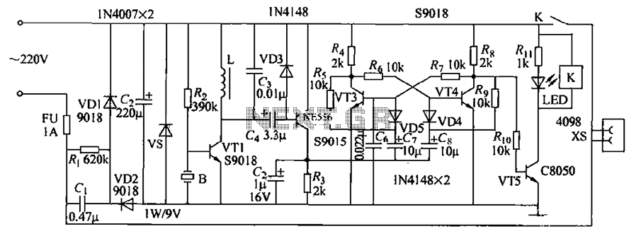
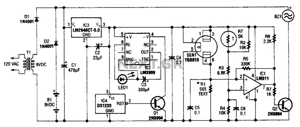
In summary, this alert system offers a convenient and effective solution for notifying individuals of events or conditions within a home, leveraging existing electrical infrastructure for seamless communication.Pressing the pushbutton of the transmitter, a sound and/or light alert is activated in the receiver. The system uses no wiring or radio frequencies: the transmitted signal is conveyed into the mains supply line. It can be used at home, in any room from attic to cellar, simply plugging transmitter and receiver in the wall mains sockets.
Transmission range can be very good, provided both units are connected to the mains supply within the control of the same light-meter.. 🔗 External reference
Related Circuits
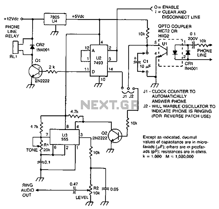
Check the loop circuit for an automatic telephone answering system or a tone generator for use in reverse automatic repair. The loop circuit in an automatic telephone answering system is designed to detect incoming calls and activate the answering mechanism....
Asia ultrasonic remote control switch. This example describes the use of a gas pressure bisulfite ultrasound flute (made of rubber, available in olive and flat round shapes) for control. When the ultrasonic flute is activated, the remote control switch...
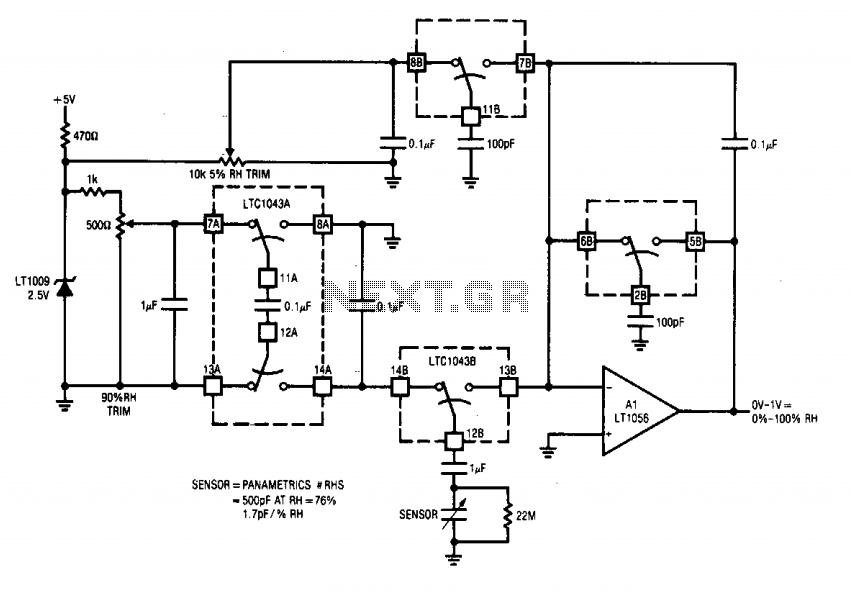
This circuit integrates two LTC1043 devices with a humidity transducer based on a charge-pump configuration. The specified sensor has a nominal capacitance of 400 pF at a relative humidity (RH) of 76%, exhibiting a slope of 1.7 pF/% RH....
This triac-based 220V AC motor speed controller circuit is designed for controlling the speed of small household motors, such as drill machines. The motor speed can be adjusted by altering the setting of P1, which determines the phase of...
The example below illustrates the use of an operational amplifier (op-amp) as an audio amplifier in a basic intercom system. A small 8-ohm speaker is utilized as a microphone, which is connected to the op-amp input through a 0.1...
The gas sensor primarily consists of tin dioxide mounted on a ceramic substrate. The sensor's resistance changes based on the concentration of reducing gases present in the air. The depicted circuit is effective for detecting hazardous levels of combustible...
Warning: include(partials/cookie-banner.php): Failed to open stream: Permission denied in /var/www/html/nextgr/view-circuit.php on line 713
Warning: include(): Failed opening 'partials/cookie-banner.php' for inclusion (include_path='.:/usr/share/php') in /var/www/html/nextgr/view-circuit.php on line 713