
AC input circuit
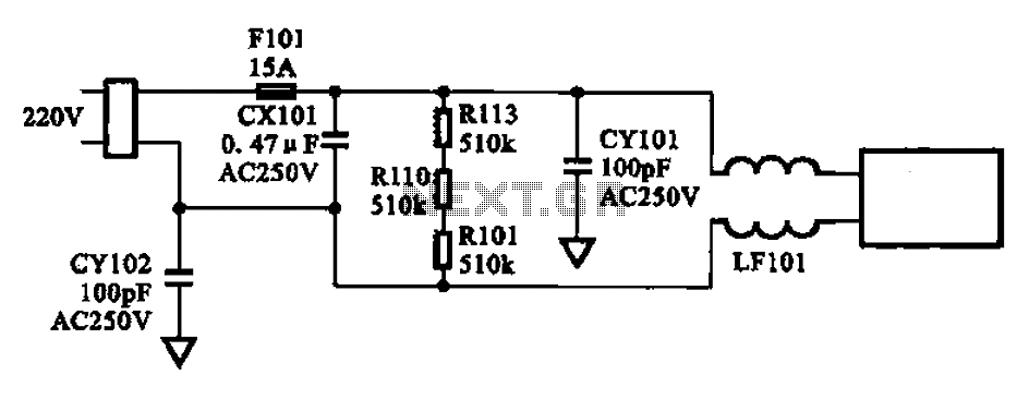
The AC input circuit is a crucial component in power supply designs, ensuring that the incoming AC voltage is clean and stable for subsequent processing. The fuse (Fl01) serves as a protective device that disconnects the circuit in the event of an overcurrent condition, thus preventing damage to downstream components.
The mutual inductance filter (LF101) is designed to reduce high-frequency noise by utilizing the principle of inductive coupling between its coils. This filter is particularly effective in attenuating electromagnetic interference (EMI) that may be present in the AC supply.
The filter capacitors (CX101, CY101, CY102) play a vital role in smoothing out voltage fluctuations and providing a low-impedance path to ground for high-frequency noise. CX101 is typically placed in parallel with the load to bypass high-frequency signals, while CY101 and CY102 are often used for common-mode noise filtering, ensuring that any noise present on the AC line is effectively shunted to ground.
The overall layout of the AC input circuit is designed to minimize inductance and resistance, which helps in maintaining signal integrity and reducing losses. Proper placement of components is essential to ensure optimal performance, with critical attention given to the grounding and shielding of the circuit to further enhance noise immunity.
In conclusion, the AC input circuit is a well-structured assembly of protective and filtering elements that work together to ensure a clean power supply, thereby enhancing the reliability and performance of electronic devices.AC input circuit AC input circuit AC input circuit is a fuse Fl01, mutual inductance filter LF101, filter capacitor CX101, CY101, CY102 and some other structure into its main f unction is to filter the AC circuit noise and pulse interference, as Figure 2-37 shows AC input circuit.
Related Circuits
High-quality, discrete component design for input and tone control modules to complement the 60-watt MOSFET audio amplifier with a high-quality preamplifier design. The circuit design focuses on creating a high-fidelity audio preamplifier that enhances the performance of a 60-watt MOSFET...
S1 and S2 are normally open, push-to-close, momentary switches. The diodes can be either red or green and are used solely for indicating direction. The TIP31 transistors may need to be adjusted based on the motor specifications. It is...

To prevent deep discharge that can damage or shorten the life of a rechargeable battery, it is essential to disconnect its load before the battery is completely discharged. The circuit protects against AC line disturbances by switching off the...
The integrated circuit LA3607 enables the configuration of a 7-band graphic equalizer for a single audio channel by incorporating additional capacitors and variable resistors. The cutoff frequency can be modified using variable resistors. It demonstrates high stability when handling...

This document outlines the design process of a control circuit for a stepper motor. Given the characteristics of the stepper motor, the control circuit was developed as a state machine that transitions through four output states depending on two...
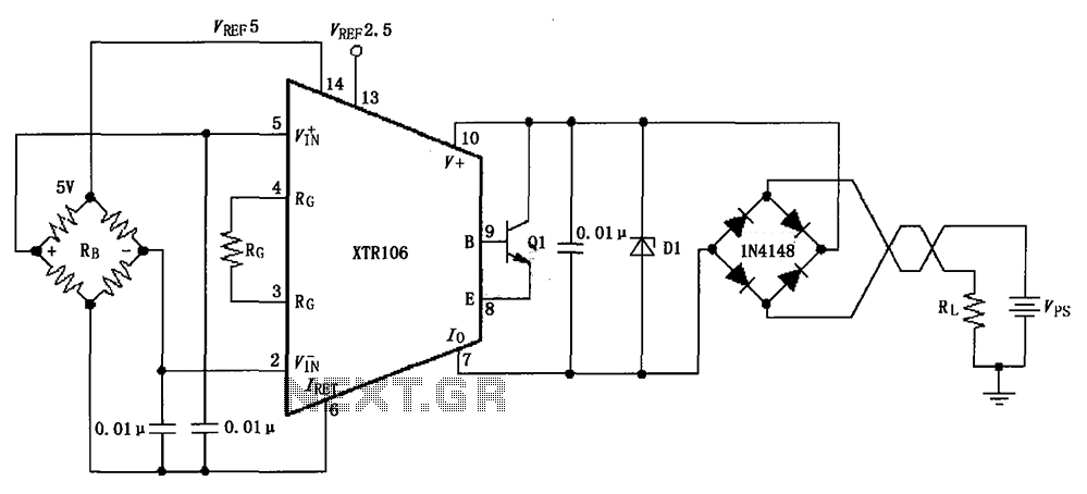
The circuit utilizes a Zener diode D1 to limit surge voltage and incorporates a four-diode rectifier bridge to prevent reverse voltage. The Zener diode D1 is rated at 36V, with optional choices being 1N4753A or 6KE39A. When the loop...