
DC Motor Control Circuit
The circuit described employs two normally open push-button switches, S1 and S2, which serve as user interfaces to control the operation of a small motor. When either switch is pressed, it completes the circuit, allowing current to flow to the motor, which in turn opens or closes the curtains. The use of momentary switches provides a manual control mechanism, permitting the user to adjust the position of the curtains to their desired level, thus allowing for customization of light entry into the room.
The diodes incorporated into the circuit, which can be red or green, function primarily as indicators of the motor's rotational direction. This visual feedback is essential for users to understand the current state of the curtains. The choice of diodes can be adapted based on aesthetic preferences without affecting the circuit's functionality.
The TIP31 transistors are utilized to amplify the current supplied to the motor, enabling it to operate effectively. Depending on the specifications of the motor in use, the transistors may require replacement with alternatives that can handle the necessary current and voltage ratings. It is crucial to consider that motors under load will draw more current, necessitating the selection of transistors with appropriate ratings to prevent overheating and ensure reliable operation.
The circuit also includes four back EMF diodes positioned around the motor. These diodes are critical for protecting the circuit from voltage spikes that occur when the motor is turned off, which can potentially damage other components. The selection of these diodes must align with the motor's specifications; for instance, using 1N4001 diodes is suitable for a 12V motor drawing 1A under load, as they can effectively handle the reverse voltage generated by the motor.
Overall, this circuit design provides a practical solution for controlling curtain movement, balancing user control with the benefits of motorized operation, while ensuring protection against electrical transients.Here, S1 and S2 are normally open, push to close, press button switches. The diodes can be red or green and are there only to indicate direction. You may need to alter the TIP31 transistors depending on the motor being used. Remember, running under load draws more current. This circuit was built to operate a small motor used for opening and closi ng a pair of curtains. As an advantage over automatic closing and opening systems, you have control of how much, or how little light to let into a room. The four diodes surriunding the motor, are back EMF diodes. They are chosen to suit the motor. For a 12V motor drawing 1amp under load, I use 1N4001 diodes. 🔗 External reference
Related Circuits

The LM4819 audio power amplifier is designed to amplify audio signals. An audio signal is input through the coupling capacitor (Ci) and the resistor (Ri) applied to the inverting input terminal (pin 3) of the amplifier. The inverting input...

Power an RS232-TTL converter circuit using the serial port to eliminate the need for an external power supply. It has been noted that the DTR, RTS, and TD pins can facilitate this. Since the TD pin is already utilized...

Diode D1 and resistor R1 provide VDD isolation during the programming of 24-pin devices. Jumper J3 must be shorted for 24-pin devices and left open for programming 28-pin devices. The following EEPROMs are pin compatible with their EPROM versions. In...

A design for a digitally controlled analog oscillator is being developed. The control voltage is generated by a microcontroller (Arduino) and is utilized through two operational amplifiers, along with a resistor and capacitor network that forms an integrator circuit....
This is a straightforward water level buzzer circuit designed to detect the water level in tanks, pools, washing machines, and similar applications. The circuit features two probes that, upon contact with water, trigger the buzzer to emit a sound....
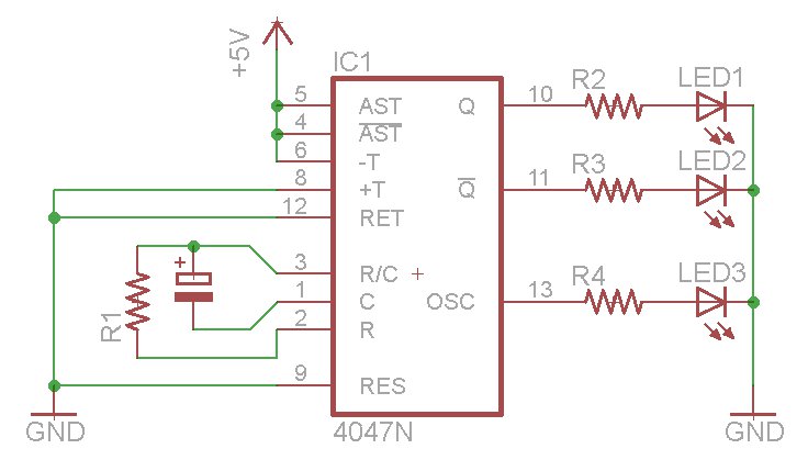
The oscillator output generates a signal that is approximately twice the frequency of Q. The other pins will be considered subsequently. In a brief video demonstration, LEDs are connected to all three outputs, illustrating the alternating behavior of Q...