
NOT circuit

The common-emitter transistor amplifier is a widely used configuration in analog electronics, characterized by its ability to provide voltage gain and inverting characteristics. In this setup, the transistor operates in its active region, allowing for efficient signal amplification. The input signal is applied to the base terminal of the transistor, while the output is taken from the collector terminal. Due to the nature of the common-emitter configuration, a positive change in the input voltage results in a negative change in the output voltage, leading to the inverting behavior.
The circuit typically includes biasing resistors to establish the correct operating point for the transistor, ensuring linear operation and minimizing distortion. Capacitors may also be employed to couple the input and output signals while blocking DC components, allowing for AC signal amplification.
The NAND gate configuration mentioned refers to a specific logic gate that outputs a low signal only when all its inputs are high. This logic function can be implemented using combinations of transistors, diodes, or integrated circuits, depending on the desired application. The versatility of the common-emitter amplifier makes it suitable for various applications, including signal conditioning, audio amplification, and as a building block for more complex circuits.
DTL, TTL, and C-MOS technologies represent different approaches to digital logic design. DTL circuits utilize diodes to perform logic functions, making them simpler but slower compared to TTL circuits, which use transistors for faster switching speeds and better noise margins. C-MOS technology, on the other hand, is known for its low power consumption and high packing density, making it suitable for modern digital applications.
Overall, the common-emitter amplifier and associated logic circuits form the cornerstone of many electronic systems, enabling efficient signal processing and logic operations essential for various applications in telecommunications, computing, and control systems.A common-emitter transistor amplifier, the opposite phase output signal of the input signal, also known as an inverting amplifier. As this electrical path for amplifying the pu lse signal from the inverting amplifier is enabled, this circuit is a non-A circuit, that is, NAND gate logically. Is an integrated circuit made by a non-shown in FIG. gates, namely the inverter, the output signal of the opposite phase to the input, positive polarity pulse input impulse, the output is reverse polarity pulse gate logic signal processing system is the basic unit circuit, it has DTL type, TTL type and the C-MOS type three .DTL is diode Tranaistor logic (diode-transistor logic) is the abbreviation .TTL transistor transistor logic (transistor transistor logic) for short.
the difference between these two is dTL logic circuit uses a diode for the input circuit. TTL uses transistors as the input path .C-MOS is an abbreviation for Complementary MetaJ Oxide Semiconductor, this circuit is mainly used C-MOS FET logic circuit of tubes.
Related Circuits
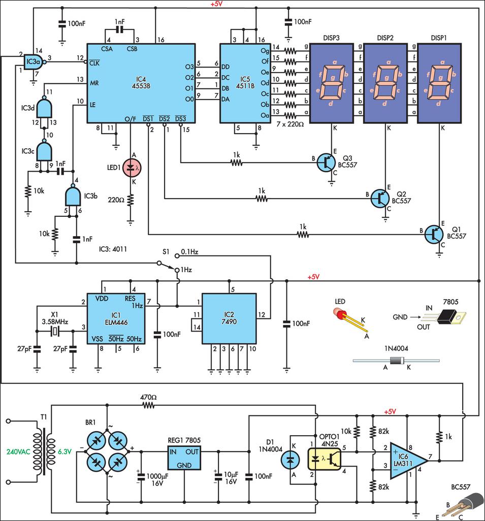
This is a simple frequency counter designed to monitor the 240VAC mains supply. It has a frequency range of 0-999Hz, making it suitable for use with 400Hz equipment as well. Standard TTL/CMOS logic is utilized for the counters and...
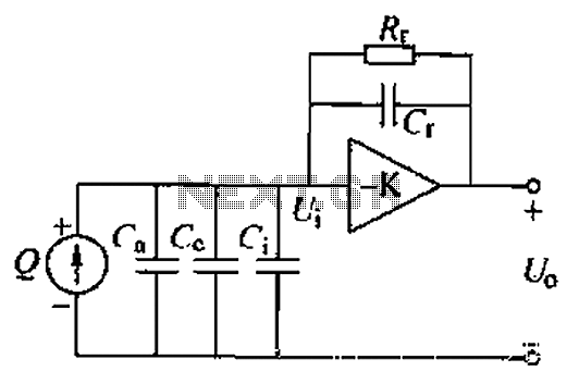
A charge amplifier is an effective device for measuring punch hits. This amplifier utilizes a negative feedback capacitor in conjunction with a high-gain operational amplifier. The amplifier operates with minimal shunt, relying primarily on the feedback capacitor's charge (q...
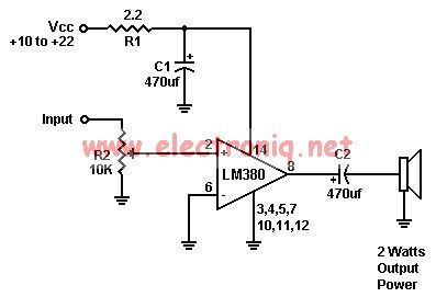
A simple audio amplifier can be designed using the LM380 along with a few external components. This amplifier features a wide supply voltage range, an input impedance of 150 kΩ, low distortion, and a current capability of 1.3 A. The...
Here are some circuit diagrams for driving relays from a microcontroller. Ensure the use of a 5-volt relay (this refers to the coil, not the load circuit) and verify that the relay has a sufficient rating for the load...
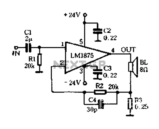
A current-sense amplifier is utilized to enhance the performance of the LM1875 current-mode amplifier circuit, as depicted in Figure 5-20. The resistor R3 and the series resistance of the speaker contribute to the current flowing through R3. This current...
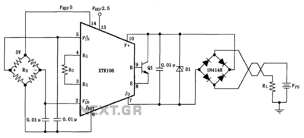
The circuit utilizes a Zener diode D1 to limit surge voltage and incorporates a four-diode rectifier bridge to prevent reverse voltage. The Zener diode D1 is rated at 36V, with optional choices being 1N4753A or 6KE39A. When the loop...