
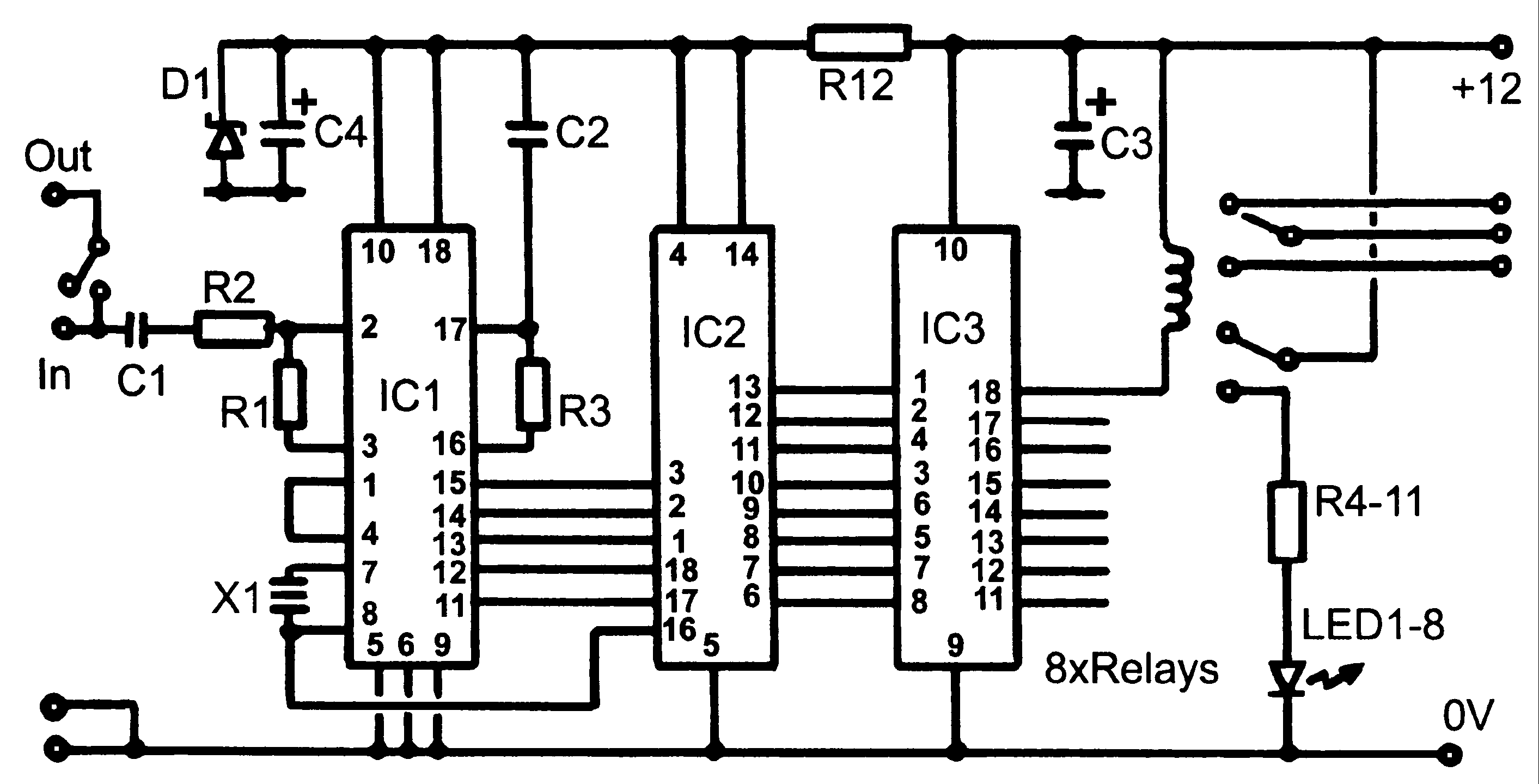
relay circuit diagram
The circuit diagrams for driving relays from microcontrollers typically include essential components such as the microcontroller itself, a relay module, and supporting components like resistors, diodes, and transistors. The microcontroller outputs a control signal to the base of a transistor, which acts as a switch to drive the relay coil. The transistor amplifies the current from the microcontroller, enabling it to control the relay, which can handle higher voltage and current loads.
In the case of a 5-volt relay, the relay coil is connected to the collector of the transistor, while the emitter is grounded. A resistor may be placed between the microcontroller output pin and the base of the transistor to limit the current flowing into the base. A flyback diode is typically connected in parallel with the relay coil to prevent voltage spikes generated when the relay is turned off, which could damage the microcontroller.
For relays that can be directly activated by the microcontroller, such as reed or solid-state relays, the circuit is simplified since no additional components like transistors are required. The microcontroller can switch these relays directly, provided they operate within the microcontroller's current and voltage specifications.
When dealing with AC loads, the relay contacts should be rated for the AC voltage and current being switched. Proper labeling of the relay pins is crucial for ensuring correct connections. It is imperative to construct the AC circuit safely, ensuring that the relay coil is tested and operational before connecting any AC load. Safety precautions must be taken to avoid direct connections of AC voltage to the relay coil, and if there is any uncertainty regarding the circuit, it is advisable to consult with an experienced individual for verification.Here`s are some circuit diagrams for driving relays from a microcontroller. Make sure you`re using a 5-volt relay (this refers to the coil, not the load circuit), and make sure that the relay has a high enough rating for the load that you`re driving. This circuit is necessary if you are using a relay with a coil that needs more power than the micr ocontroller can supply (this includes most miniature electromechanical relays): Some relays (such as reed relays and solid-state relays) have coils that can be switched directly from the microcontroller, in which case you can use a less complex circuit: Finally: if you`re switching an AC device, PLEASE BE CAREFUL. Make sure you`ve got the coil working BEFORE you hook up the AC load. Make sure you have correctly labeled all the pins on the relay NEVER connect AC voltage directly to the relay coil.
Build your AC circuit BEFORE you plug it in. If you`re not sure, ask someone to check it for you first. 🔗 External reference
Related Circuits
Control monitoring equipment at a TV repeater site is designed to accept commands sent as DTMF tones over the repeater's audio channel. It is capable of switching either AV signals or power supply feeds with currents up to 1...
This circuit generates a sound similar to that of ambulance sirens. It differs from typical ambulance siren circuits in its design. The circuit utilizes a combination of oscillators and amplifiers to produce a sound that mimics the varying pitch and...
The thermocouple cold junction compensation circuit and the MAX6675 converter circuit diagram form a temperature measuring system. The system utilizes a K-type thermocouple connected to the T terminals of the MAX6675, with the cold junction grounded. An 8051 microcontroller...

The following diagram represents a Clock Generator circuit that is constructed using NAND Gate logic integrated circuits (ICs). The circuit can utilize either IC 7400 or IC 4011. The 7400 is a TTL (Transistor-Transistor Logic) type, whereas the 4011...
Light flashing circuit. This circuit is designed to create a small lamp that flashes with a signal at a rate of one flash per second, controlled by adjusting the lamp voltage through resistor R1. The rate is adjustable to...
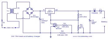
To set up the charging voltage, power on the charger and connect a voltmeter across the output terminals. Adjust R4 until the voltmeter reads 28V. The charger is now ready for battery connection. The charging circuit described involves a voltage...