
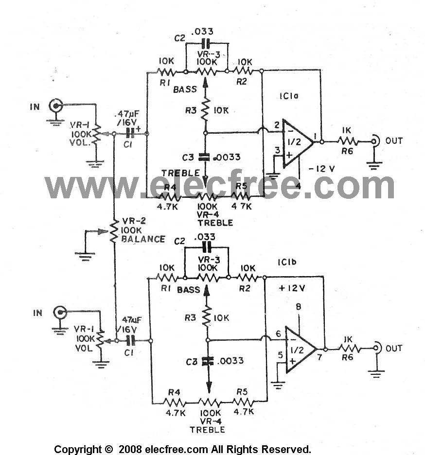
OTL amplifier circuit diagram
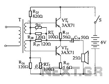
The OTL amplifier circuit operates by directly connecting the output stage to the speaker without the use of a traditional output transformer. This design is advantageous as it minimizes the weight and bulk of the amplifier while maintaining high fidelity audio output. The 100 mW power rating indicates that the circuit is suitable for low to moderate volume applications, typically found in consumer electronics like radios and small audio amplifiers.
In terms of design, the OTL amplifier utilizes transistors or vacuum tubes in its output stage, which are selected for their linear amplification characteristics. The choice of components significantly affects the overall performance, including distortion levels and frequency response. The inclusion of a capacitor in the output stage serves to block any DC offset, ensuring that only the AC audio signal reaches the speaker. This capacitor must be carefully chosen to handle the expected frequency range and power levels without introducing significant phase shift or distortion.
The frequency response of the OTL amplifier is crucial, particularly in radio applications where clarity and fidelity are paramount. The circuit is designed to have a flat frequency response across the audible range, typically from 20 Hz to 20 kHz. This is achieved through careful component selection and layout, ensuring that signal integrity is maintained throughout the circuit.
The efficiency of the OTL amplifier is another key feature, as it allows for longer operation times in battery-powered devices and reduces heat generation, which can enhance reliability. The low nonlinear distortion characteristic is particularly beneficial, as it ensures that the audio output remains true to the original signal, providing a more enjoyable listening experience.
Overall, the OTL amplifier circuit represents a sophisticated solution for applications requiring compact, efficient, and high-quality audio amplification. Its design principles and operational characteristics make it a valuable component in modern electronic devices, particularly in the realm of audio and broadcasting technologies.The following diagram shows an output power of radio 1OOmW common OTL amplifier circuit. The circuit output transformer, and a capacitor together with the speaker units. Frequency characteristics OTL amplifier circuit with good nonlinear distortion characteristics and high efficiency, widely used in televisions, amplifiers and other electronic devices. FIG OTL amplifier circuit diagram of the radio
Related Circuits
The final project involves cycling rollers that require a method to sense the rotational speed of one of the rollers. Speed sensors on bicycles typically function by detecting a magnet attached to a spoke on one of the wheels...
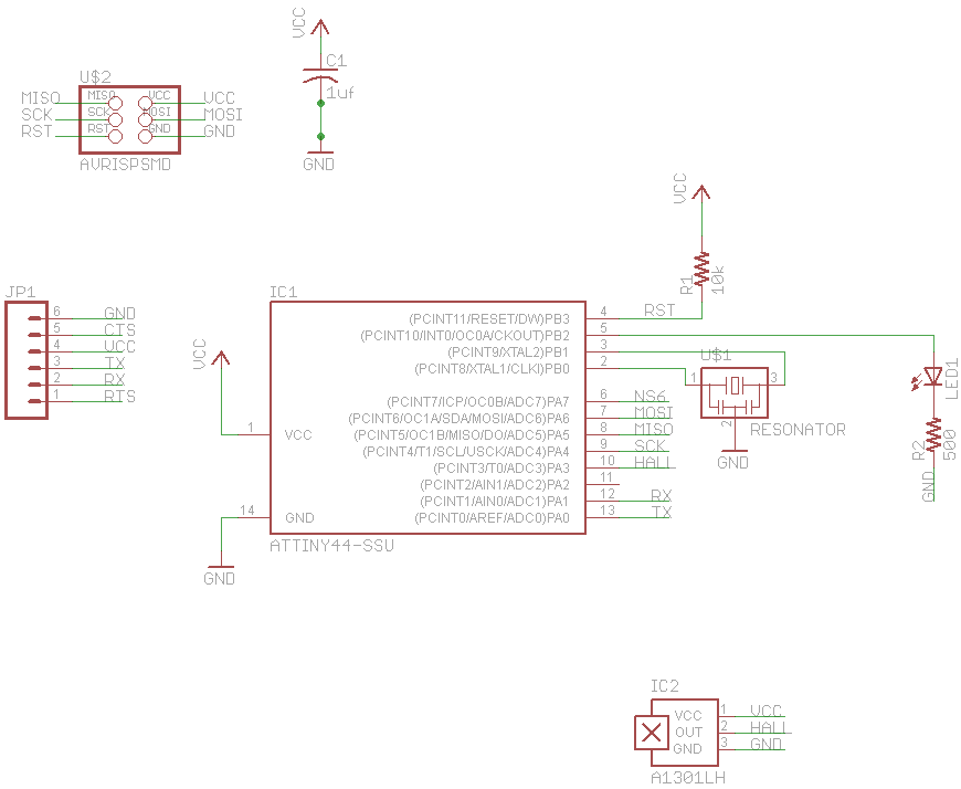
The IR Jammer is a fun project that provides a bit of safe, non-destructive fun. The Infrared Remote Control Jammer allows you to render all IR remote controls inoperative! The microcontroller in this design allows for all 6 of...
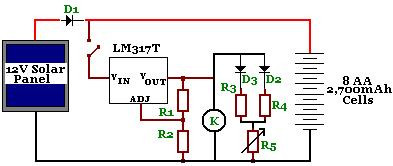
The circuit is designed to power a CCTV camera, provide lighting inside a nestbox, and charge batteries using a photovoltaic (PV) solar panel. It includes a circuit diagram for a solar-powered wireless CCTV camera with battery backup. D1 is...

This circuit generates a siren sound when switch S1 is pressed. The sound frequency increases as capacitor C1 charges, and when switch S1 is released, the frequency decreases as capacitor C1 discharges. The circuit operates on a simple principle of...
A high-quality preamplifier with tone controls consisting of three circuits. The NE5532 is chosen as the main integrated circuit due to its ultra-low noise properties, making it a popular choice in fine audio applications. Although these circuits are older...
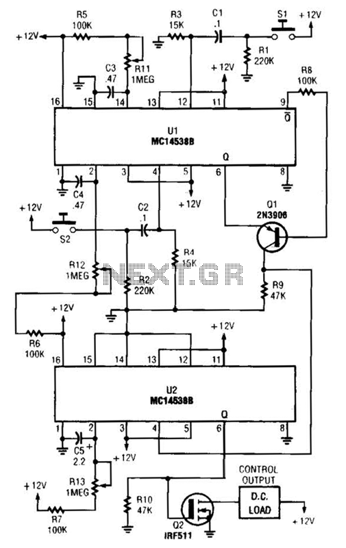
When switch SI is closed, pin 9 of operational amplifier U1 goes low, activating transistor Q1 for a predetermined duration. If switch S2 is closed during this time, transistor Q2 is activated for another predetermined duration. Resistors R1 and...