
Outband descrambler
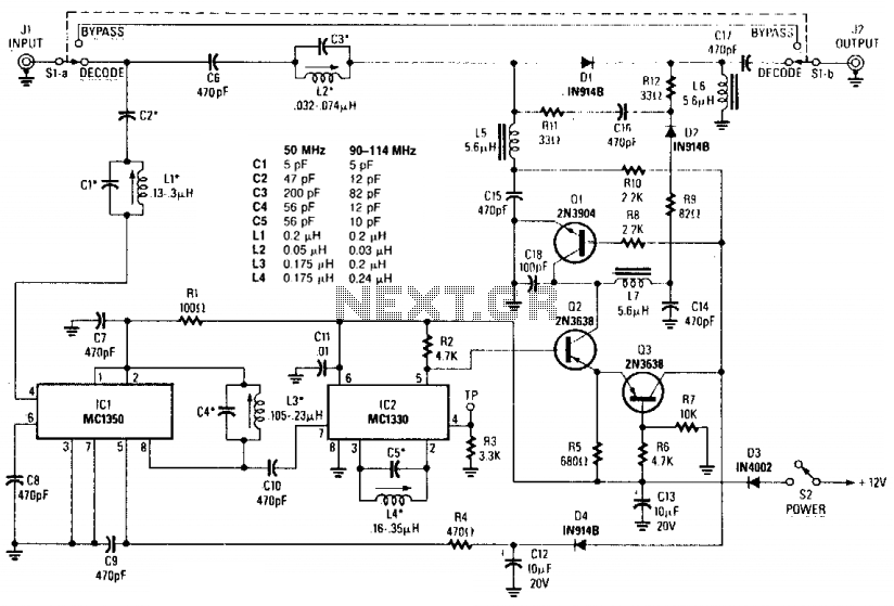
The outband descrambler circuit is designed to decode scrambled television signals by utilizing a specific signal strength to ensure proper operation. The circuit architecture features a dedicated amplifier that enhances the synchronization channel, which is essential for maintaining signal integrity during the decoding process.
The video detector plays a crucial role in monitoring the incoming signals and adjusting the gain of the amplifier through an attenuator. This adjustment is particularly important during synchronization intervals, where the gain is increased to ensure that the decoder can accurately interpret the signal.
Capacitors C1-C5 and inductors L1-L4 are carefully selected based on their values listed in Table 1, which are critical for tuning the circuit to the desired frequency range and optimizing performance. The arrangement of these components influences the overall bandwidth and response characteristics of the circuit, ensuring that it can handle the variations in signal strength that may occur during operation.
In summary, the outband descrambler circuit is a sophisticated system that relies on precise component values and signal management techniques to effectively decode scrambled signals, providing users with access to a broader range of television programming.For the outband decoder shown here to work, the cable company must provide at least a 1 millivolt signal. Values for C1-C5 and L1-L4 ore found In Table 1. This circuit consists of an amplifier for the synch channel and a video detector which controls an attenuator so that the gain of the systems is increased dining synch intervals.
Outband descrambler circuit 🔗 External reference
Related Circuits
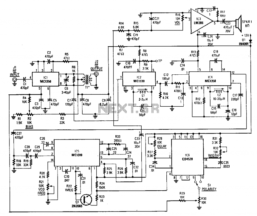
This decoder incorporates a sine wave recovery channel and utilizes a PIN diode attenuator driven by the sine wave recovery system to eliminate the sine wave sync suppression signal. Additionally, it functions as a sine wave descrambler. The decoder's sine...
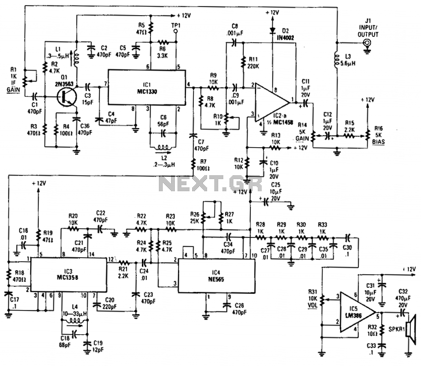
This circuit includes an amplifier and a video detector along with a secondary subcarrier detector for synchronization recovery. A pulse-former circuit modulates the gain of the main channel, enhancing it during synchronization intervals. Additionally, there is a provision for...
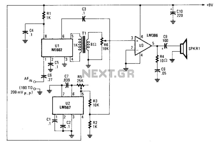
This circuit utilizes an NE602 as an inversion mixer. The operational frequency for U2 is set to approximately 2.5 to 3.5 kHz. U3 is responsible for driving a loudspeaker. Due to the nature of speech inversion scrambling being its...